Eureka AIR delivers breakthrough ideas for toughest innovation challenges, trusted by R&D personnel around the world.

Fuel assembly and a tubular element for a nuclear boiling water reactor

a technology of nuclear boiling water reactor and fuel assembly, which is applied in the direction of reactor fuel elements, nuclear energy generation, climate sustainability, etc., can solve the problems of increased wall temperature of fuel rods, poor moderator of steam at the upper part of the fuel assembly, and increased risk of dry out of the upper portion of the full-length fuel rods, so as to improve cooling and facilitate the arrangement of the tubular element. , the effect of reducing the risk of dry out of the upper portion of th

Inactive Publication Date: 2004-03-04
WESTINGHOUSE ATOM
View PDF30 Cites 4 Cited by
  • Summary
  • Abstract
  • Description
  • Claims
  • Application Information

AI Technical Summary

Benefits of technology

"The present invention relates to a fuel assembly for a nuclear boiling water reactor that improves cooling of the full-length fuel rods. The fuel assembly includes a plurality of full-length fuel rods, a part-length fuel rod, and a tubular element. A cooling medium flows upwardly through the fuel assembly during operation. The invention achieves improved cooling by guiding the cooling medium in a specific direction and allowing it to flow through the fuel rods in a more efficient manner. This results in a higher reactivity of the reactor and better security."

Problems solved by technology

Since the steam has a relatively low density, the steam at the upper part of the fuel assembly is a poorer moderator than the water in the lower part of the fuel assembly.
This results in a locally deteriorated heat transfer between the fuel rod and the water flowing through the fuel assembly.
This results in its turn to an increased wall temperature of the fuel rods.
The increased wall temperature may result in serious damages on the fuel rod.
Such a pressure drop results namely in losses of effect.
Furthermore, it has been proved that this kind of flow influencing element described in said document results in a relatively great pressure drop in the fuel assembly.
It is relatively uncomplicated to shape a plug to have a suitable surface for deflecting the cooling medium flow.

Method used


Image

  • Fuel assembly and a tubular element for a nuclear boiling water reactor
  • Fuel assembly and a tubular element for a nuclear boiling water reactor
  • Fuel assembly and a tubular element for a nuclear boiling water reactor

Examples


Embodiment Construction

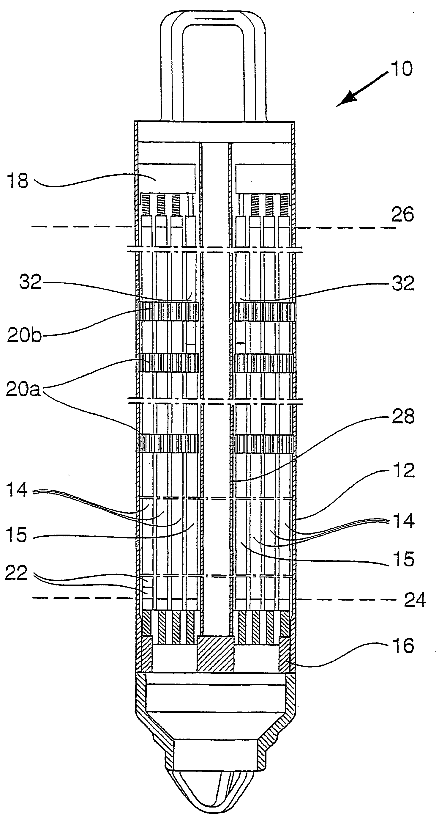
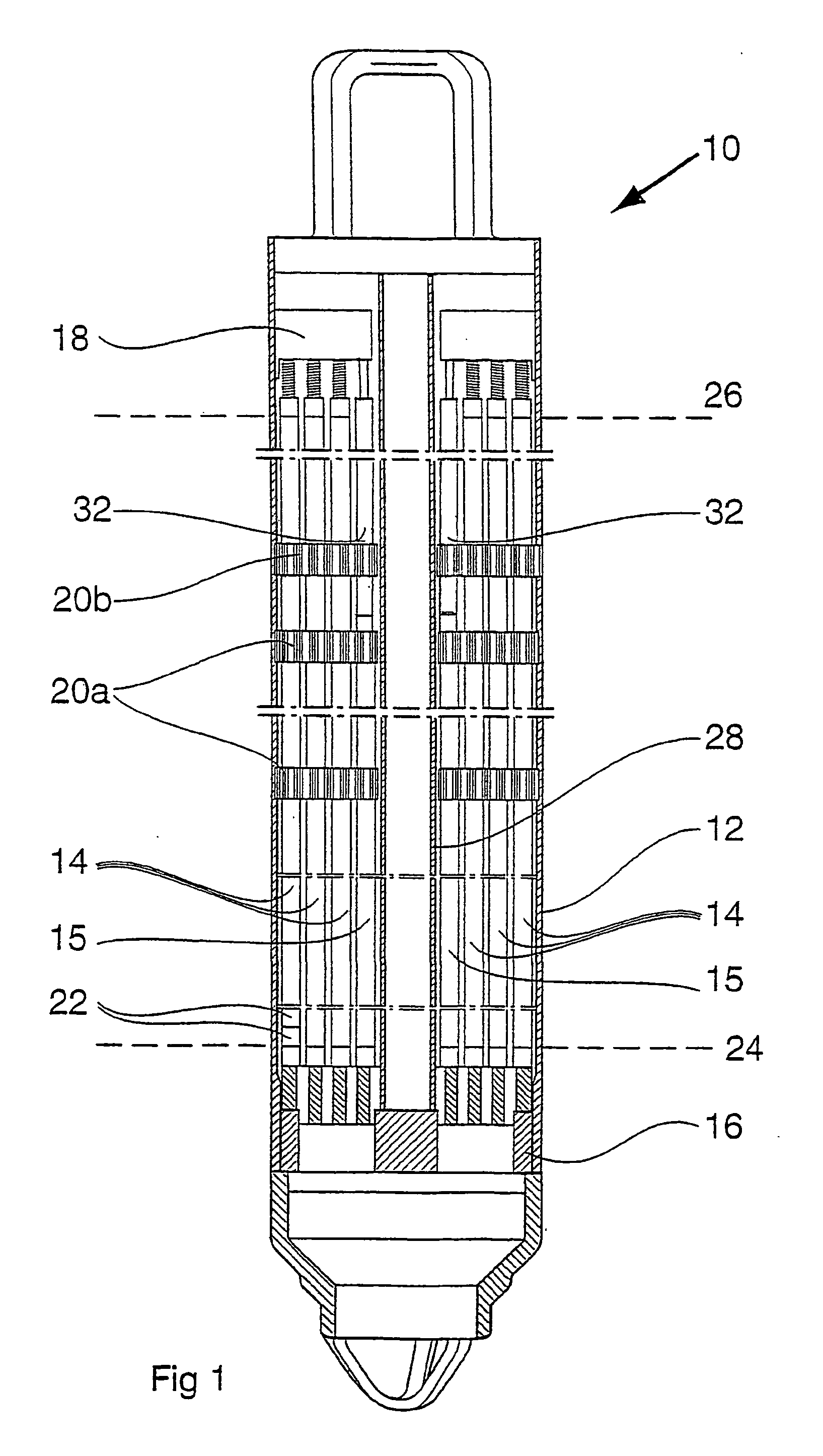
[0024] FIG. 1 shows a vertical section through a fuel assembly 10. The fuel assembly 10 comprises an external casing wall 12, which encloses a number of fuel rods 14, 15 arranged in the fuel assembly 10. Usually, the fuel rods 14, 15 are arranged in parallel with each other and have an extension in a vertical direction. However, it ought to be noted that the fuel rods 14, 15 do not necessarily have to be arranged vertically and in parallel with each other. There are fuel assemblies 10 with fuel rods 14, 15 having a certain inclination. The fuel rods 14, 15 comprise pellets 22 of nuclear fuel material, for example, in the form of uranium dioxide. The fuel rods 14, 15 are kept in place in bundles in the fuel assembly 10 by means of a bottom tie plate 16 and a top tie plate 18. In the fuel assembly, a number of spacers 20a, 20b are arranged. The spacers 20a, 20b have i.a. the function to hold the fuel rods 14, 15 at a determined distance from each other.

[0025] A part of the fuel rods 1...


PUM


Abstract

The present invention relates to a fuel assembly (10) and a tubular element (32, 32') for a nuclear boiling water reactor. The fuel assembly (10) comprises a plurality of full-length fuel rods (14), at least one part-length fuel rod (15) and at least a tubular element (32, 32'), which is arranged above the part-length fuel rod (15) in the fuel assembly (10). A cooling medium flows, during the operation of the boiling water reactor, upwardly through the fuel assembly (10) in order to cool the fuel rods (14, 15). A part of the cooling medium flow is guided into the tubular element (32, 32') through at least one inlet opening (34, 34') and out through at least one outlet opening (36). The tubular element (32, 32') comprises in the vicinity of the outlet opening (36) an internally arranged body (44, 46) having a surface (38), which deflects at least a main part of the upwardly directed cooling medium flow in the tubular element (32, 32') out through the outlet opening (36) and in a direction towards a full-length fuel rod (14).

Description

BACKGROUND OF THE INVENTION AND PRIOR ART[0001] The present invention relates to a fuel assembly and a tubular element for en nuclear boiling water reactor, wherein the fuel assembly comprises a plurality of full-length fuel rods, which extend from substantially a first level located in a lower part of the fuel assembly to substantially a second level located in an upper part of the fuel assembly, at least one part-length fuel rod, which extends substantially from said first level and upwardly but not right up to the second level, and at least a tubular element, which is arranged in an area located above the position of the part-length fuel rod in the fuel assembly, wherein a cooling medium is arranged to flow upwardly through the fuel assembly, during operation of boiling water reactor, in order to cool the fuel rods and that at least a part of the cooling medium flow which passes through said area is arranged to be guided into the tubular element through at least one inlet opening...

Claims


Application Information

Patent Timeline
Patent Type & Authority Applications(United States)
IPC IPC(8): G21C3/322G21C3/326
CPCG21C3/322G21Y2002/201G21Y2002/204Y02E30/38G21Y2004/302Y02E30/31G21Y2002/302Y02E30/30
Inventor NYLUND, OLOV
Owner WESTINGHOUSE ATOM
Why Eureka
Eureka Blog
Learn More