
Generation of trace elements within a data processing apparatus

Active Publication Date: 2004-02-12
ARM LTD
View PDF11 Cites 115 Cited by
  • Summary
  • Abstract
  • Description
  • Claims
  • Application Information

AI Technical Summary

Benefits of technology

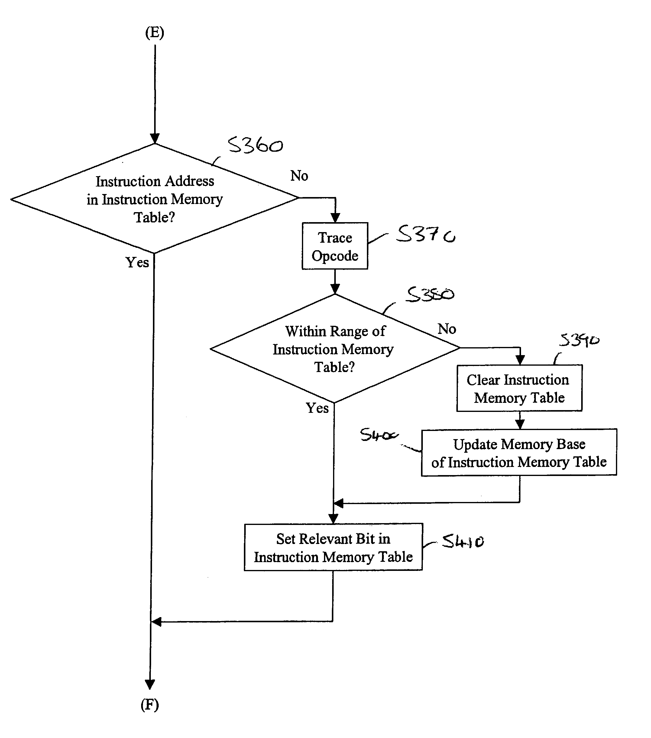
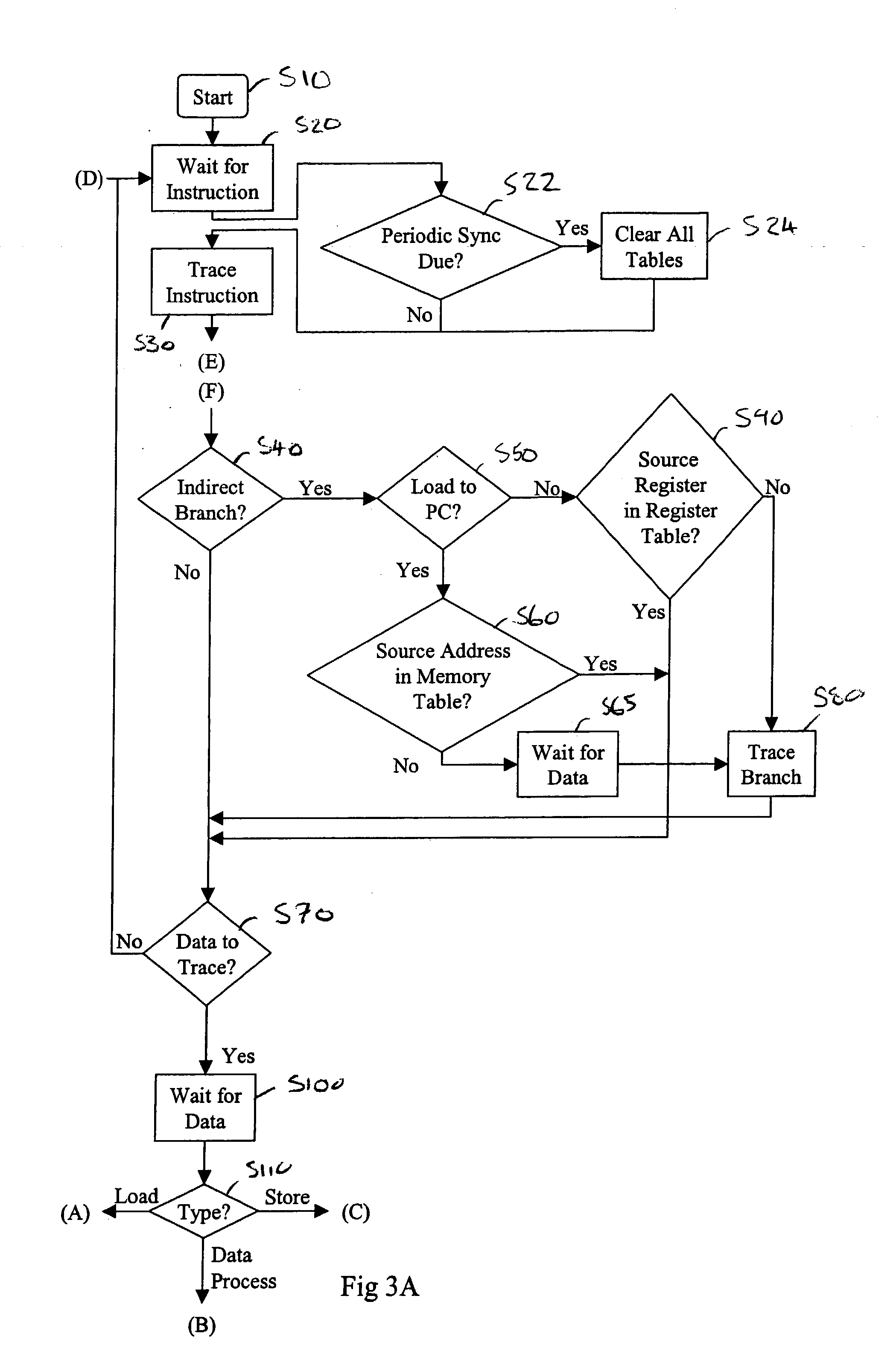
[0014] By avoiding the need to generate trace elements for all items of architectural state when tracing begins, and by only tracing the changes in architectural state that are not derivable by the recipient, the amount of architectural state that needs to be generated at any time is significantly reduced compared with prior art approaches.

Problems solved by technology

However, with the general move towards more deeply embedded processor cores, it becomes more difficult to track the architectural state of the processor core (such as the contents of registers, the values stored at particular memory locations or the status of various buses, paths, lines, flags or modules within processor core or to which the processor core is coupled) via externally accessible pins.
It has been found that the bandwidth of the dedicated data bus limits the rate at which information can be stored in the trace buffer.
As data processing systems increase in power and complexity, it is clear that the amount of architectural state and its rate of change will increase.
However, there is a problem that there is a finite bandwidth over which the trace elements to be buffered are received and the trace buffer has a finite size.
Accordingly, the volume of trace elements that can be buffered, and hence the amount of architectural state that can be reconstructed, is limited.

Method used


Image

  • Generation of trace elements within a data processing apparatus
  • Generation of trace elements within a data processing apparatus
  • Generation of trace elements within a data processing apparatus

Examples


Embodiment Construction

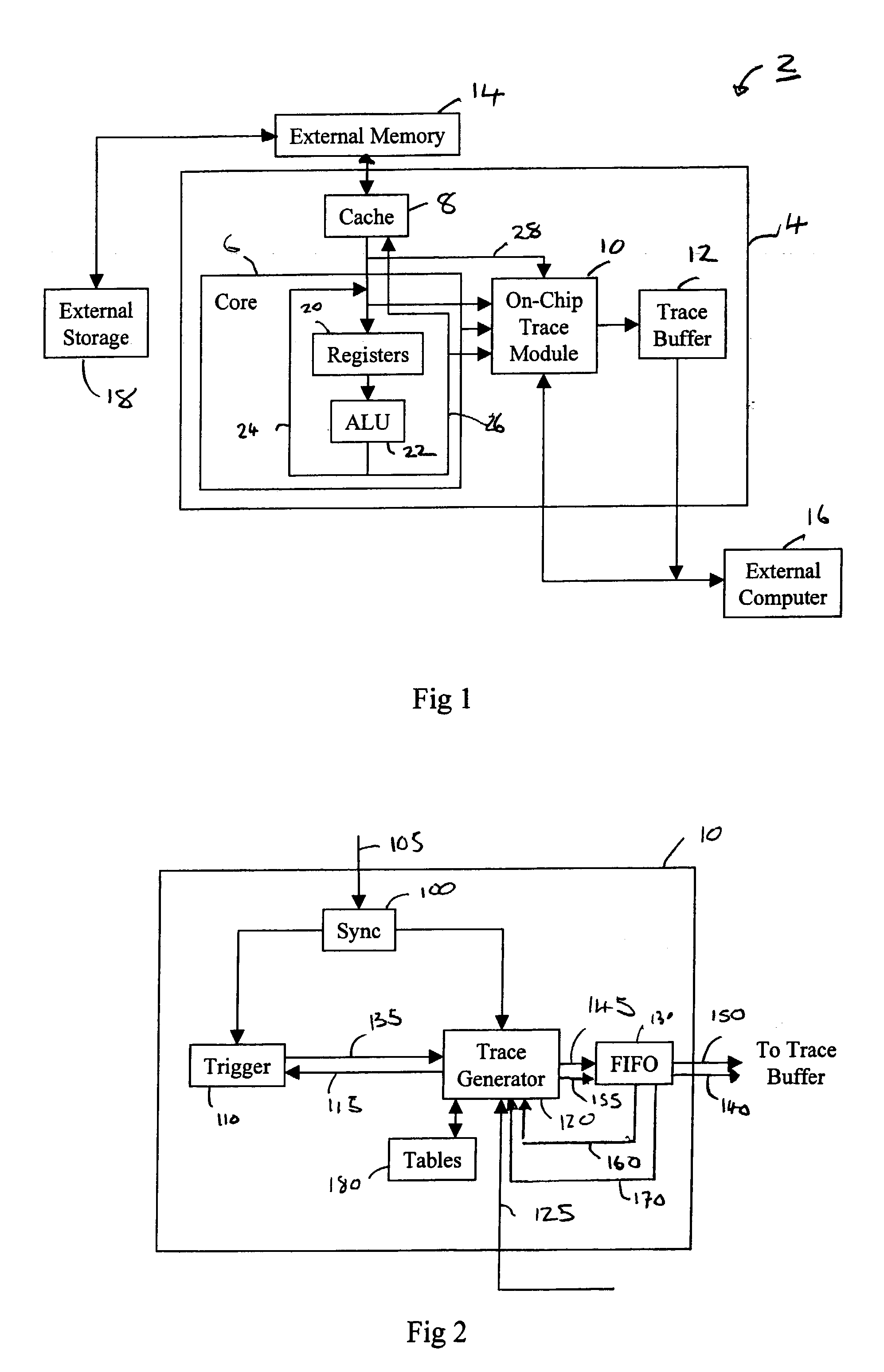
[0097] FIG. 1 schematically illustrates a data processing apparatus 2 providing an on-chip trace module. An integrated circuit 4 includes a microprocessor core 6, a cache memory 8, an on-chip trace module 10 and an on-chip trace buffer 12. It will be appreciated that whilst this illustrative embodiment shows an on-chip trace module and on-chip trace buffer 12, it will be appreciated that the trace module and / or trace buffer could instead be provided separately and coupled with the integrated circuit 4 or processor core 6.

[0098] The data processing apparatus 2 has architectural state associated therewith. Typically, some architectural state is associated with each instruction the processor core 6 is executing. Other architectural state will relate to overall operation or status of the processor core or other modules or units to which the processor core 6 or data processing apparatus 2 is coupled. Such architectural state may include the contents of registers, the values stored at par...


PUM


Abstract

The present invention relates to the generation of trace elements within a data processing apparatus having one or more components whose behaviour is to be traced. A trace module is disclosed which is operable to trace changes in a subset of architectural state of a data processing apparatus with which the trace module is coupled. The trace module comprises a trace generation unit operable to receive input signals from one or more components of the data processing apparatus indicative of a change in the subset of architectural state and to generate from one or more of the input signals a number of trace elements indicative of the change so as to enable a recipient of the trace elements to subsequently reconstruct the subset of architectural state. The trace module also comprises a table maintained by the trace generation unit to identify architectural state derivable from previously generated trace elements, the trace generation unit referencing the table in order to determine which trace elements to generate during the trace generation. By providing a table which identifies architectural state which is derivable from previously generated trace elements, the number of trace elements that need to be generated is significantly reduced. This reduction is achieved because the table provides a record of the architectural state which has already been provided to the recipient. Knowing the architectural state which has already been provided to the recipient enables the trace generation unit to determine whether changes in architectural state can be derived by the recipient. Accordingly, the trace generation unit can refer to the table and only those trace elements relating to changes in architectural state which are not derivable by the recipient need be generated. Hence, if the trace generation unit determines that the recipient is able to derive architectural state then no trace elements relating to those changes need be generated.

Description

[0001] 1. Field of the Invention[0002] The present invention relates to the generation of trace elements within a data processing apparatus having one or more components whose behaviour is to be traced.[0003] 2. Background of the Invention[0004] Tracing the activity of a data processing system whereby a stream of trace elements is generated including data representing the step-by-step activity within the system is a highly useful tool in system development. However, with the general move towards more deeply embedded processor cores, it becomes more difficult to track the architectural state of the processor core (such as the contents of registers, the values stored at particular memory locations or the status of various buses, paths, lines, flags or modules within processor core or to which the processor core is coupled) via externally accessible pins. Accordingly, as well as off-chip tracing mechanisms for capturing and analysing trace data, increased amounts of tracing functionali...

Claims


Application Information

Patent Timeline
IPC IPC(8): G06F11/28G06F9/44G06F11/34H04L1/22
CPCG06F11/25G06F11/28G06F11/3636G06F11/348G06F11/3476
Inventor SWAINE, ANDREW B.WILLIAMSON, DAVID J.
Owner ARM LTD
Learn More