Digital protection and control device
a control device and digital protection technology, applied in the direction of noise figure or signal-to-noise ratio measurement, electric programme control, instruments, etc., can solve the problem of increasing the installation space of the devi
- Summary
- Abstract
- Description
- Claims
- Application Information
AI Technical Summary
Benefits of technology
Problems solved by technology
Method used
Image
Examples
first embodiment
[0156] (Characteristics of First Embodiment)
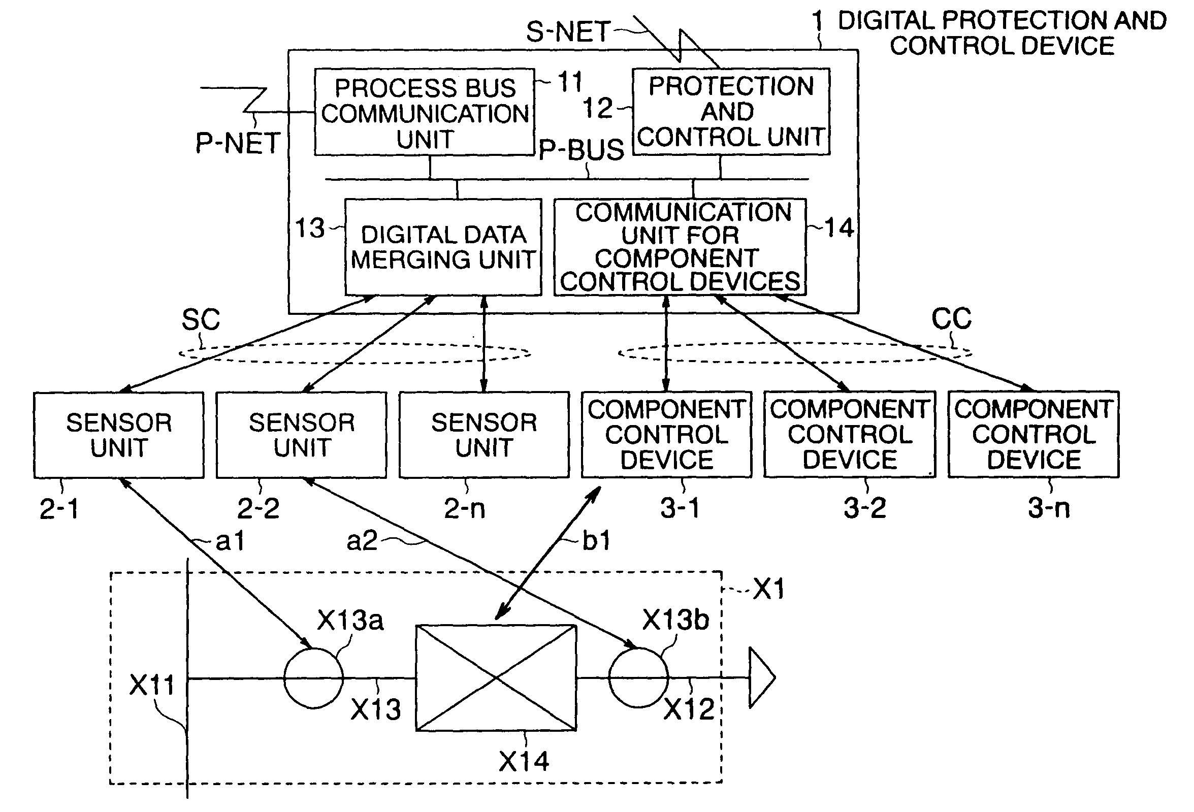
[0157] Time performance can be ensured through the use of the parallel bus P-BUS in the portions transmitting / receiving the protection and control data requiring realtime performance (for example, the portions transmitting / receiving the instantaneous value data of the AC electricity quantities of the main circuits of the substation main equipment, the transmission line for the open / close command to the circuit breaker and so on in accordance with the fault detection by the protective relay, and so on).
[0158] Here, if a certain unit among the units 11 to 14 is assigned an unbalancedly large volume of a data bus process (master process), the load of the bus process becomes large to disable the maintenance of the time performance as a whole, which causes a risk that a fault of this unit may impair data transmission / reception as the whole device. The multimaster-based transmission enables each unit to transmit / receive data independently so tha...
modification example
[0160] (Modification Example of First Embodiment)
[0161] FIG. 11 shows a modification example of the first embodiment.
[0162] In this drawing, the protection function (PU) and the control function (CU) are separated in CASE-D and CASE-C respectively, and they constitute a digital protection device and a digital control device respectively.
[0163] Here, the following shows to which components the reference symbols in the drawing correspond respectively.
[0164] PCU: the protection and control unit 12, PBCU: the process bus communication unit 11, CMCU: the communication unit 14 for component control devices, CU: the control unit 122, MU: the digital data merging unit 13, PU: the protection unit 121.
[0165] As shown in FIG. 11, the digital protection device has a configuration exclusively for protection in which all or a part of the process bus communication unit 11, the protection unit 121, the digital data merging unit 13, and the communication unit 14 for component control devices are con...
second embodiment
[0169] (Second Embodiment)
[0170] A second embodiment will be explained with reference to FIG. 12 and FIG. 13. Here, only the digital protection and control device 1 is shown. The component control devices 3-1 to 3-n and the sensor units 2-1 to 2-n are the same as those in the first embodiment, and therefore they are omitted in the drawing.
[0171] In the second embodiment, data transmission between the units among the process bus communication unit 11, the protection and control unit 12, the digital data merging unit 13, and the communication unit 14 for component control devices is in a single master mode.
[0172] In the single master mode, the unit having the bus control right is fixed. In other words, it is a transmission mode in which the master-slave relationship is fixed. For example, one of the process bus communication unit 11, the digital data merging unit 13, and the communication unit 14 for component control devices is defined as a master and all the others are defined as sl...
PUM
 Abstract
Description
Claims
Application Information
 - R&D
- Intellectual Property
- Life Sciences
- Materials
- Tech Scout
- Unparalleled Data Quality
- Higher Quality Content
- 60% Fewer Hallucinations
Browse by: Latest US Patents, China's latest patents, Technical Efficacy Thesaurus, Application Domain, Technology Topic, Popular Technical Reports.
© 2025 PatSnap. All rights reserved.Legal|Privacy policy|Modern Slavery Act Transparency Statement|Sitemap|About US| Contact US: help@patsnap.com


