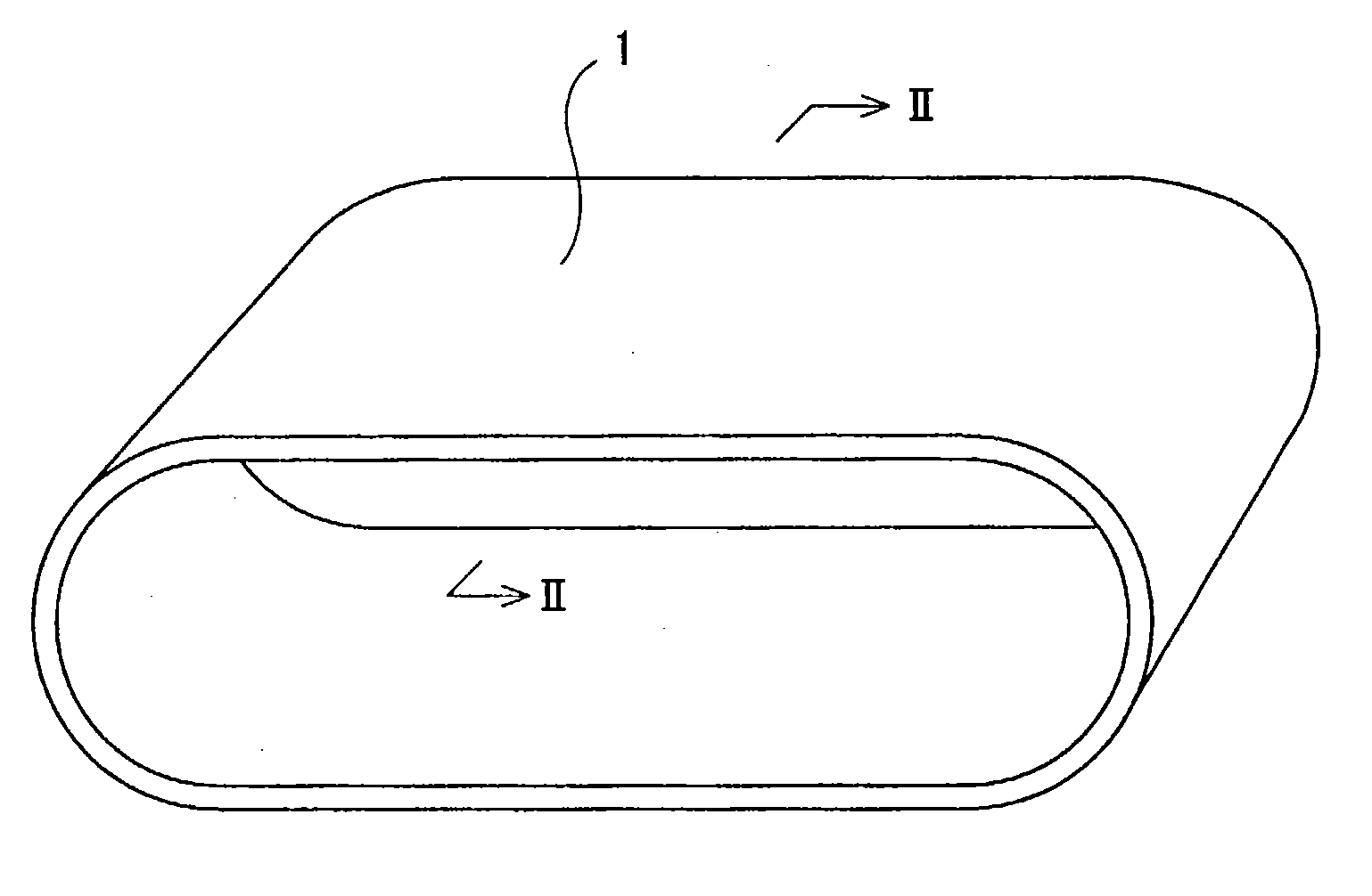
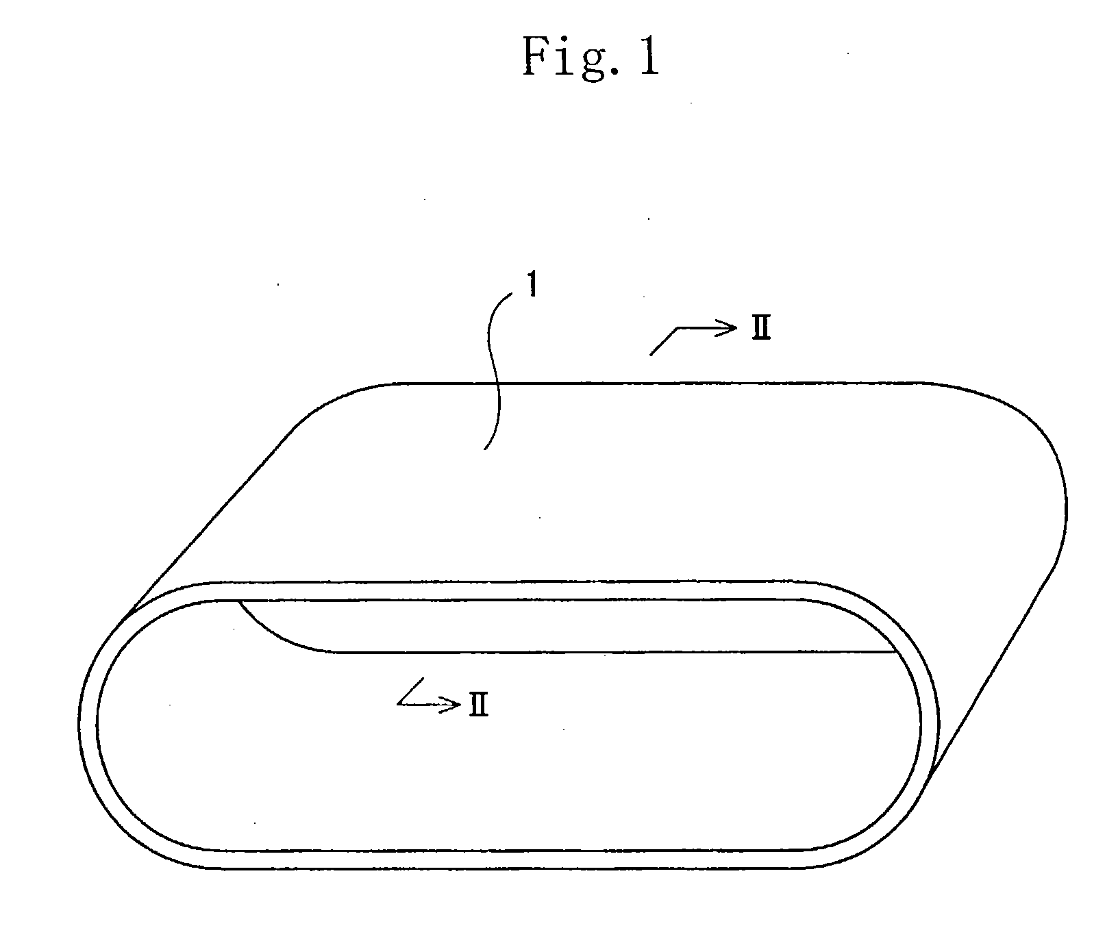
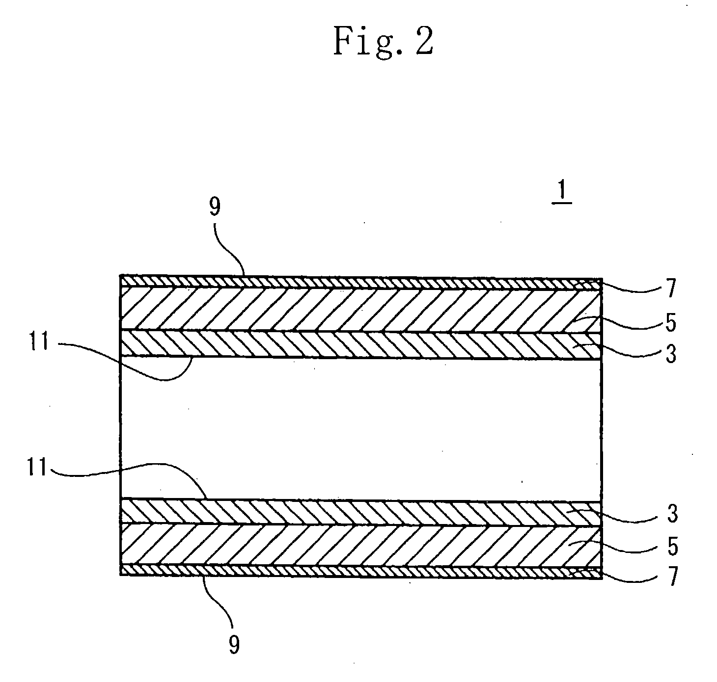
Conductive belt

a technology of conductive filler and conductive rubber, which is applied in the field of conductive belts, can solve the problems of difficult to allow the above-described resin having a high elastic modulus to be ionic-conductive, and the electric resistance varies in dependence on a portion,

Inactive Publication Date: 2004-01-22
SEIKO EPSON CORP
View PDF3 Cites 21 Cited by
  • Summary
  • Abstract
  • Description
  • Claims
  • Application Information

AI Technical Summary

Benefits of technology

[0014] The volume electric resistance value of the electroconductive resinous base layer is adjusted to not less than 10.sup.6.OMEGA..multidot-.cm nor more than 10.sup.11.OMEGA..multidot.cm by adding the electroconductive agent to the resin. The ionic-conductive intermediate layer made of the elastomer to be formed on the upper surface of the base layer has a volume electric resistance value not less than 10.sup.8.OMEGA..multidot.cm nor more than 10.sup.14.OMEGA..multidot.cm. It is possible to obtain the conductive belt having a proper conductivity and a uniform electric resistance by forming the ionic-conductive intermediate layer having high uniformity in its electric resistance in combination with the base layer having an electroconductivity imparted thereto by adding the electroconductive agent to the main component thereof and having a high elasticity and by restricting the electric resistance value of each of the base layer and the intermediate layer to a required range.
[0047] It is preferable to form the conductive belt in the order of the base layer, the intermediate layer, and the surface coating layer by repeating application of materials and hardening thereof to simplify the manufacturing process.

Problems solved by technology

In the conductive belt using the electroconductive rubber containing the conductive filler, it is difficult to disperse the conductive filler uniformly in the electroconductive rubber.
However, ionic-conductive rubber uniform in its electric resistance value does not have a high elastic modulus.
On the other hand, it is difficult to allow the above-described resin having a high elastic modulus to be ionic-conductive.
Thus both have a problem that the electric resistance varies in dependence on a portion thereof, i.e., is nonuniform in the electric resistance thereof.
Thus a preferable image cannot be obtained.
If the thickness of the intermediate layer is more than 600 .mu.m, the total thickness of the conductive belt is so large that a problem occurs in design or the intermediate layer may separate from the base layer.
On the other hand, if the thickness of the base layer is set to more than 400 .mu.m, the base layer is so rigid that there is a possibility that the base layer cracks.
If the thickness of the surface coating layer is less than 1 .mu.m, the surface coating layer is worn during use and has a inferior toner particle separation performance.
On the other hand, if the thickness of the surface coating layer is more than 50 .mu.m, it takes time and labor to form the surface coating layer and thus the cost of the material for the intermediate transfer belt is high.

Method used


Image

  • Conductive belt
  • Conductive belt
  • Conductive belt

Examples


Embodiment Construction

coating layer layer Base layer Material Coating 1 Intermediate Base layer 1 layer 1 Molding method Electrostatic Centrifugal Centrifugal deposition molding molding Thickness (.mu.) 5 300 300 Tensile modulus -- -- 640 of elasticity (Mpa) Hardness (JIS A) -- 52 --Volume 4.6 .times. 10.sup.13 2.0 .times. 10.sup.12 3.2 .times. 10.sup.8 resistivity (.OMEGA. .multidot. cm) [500 V] Ionic- Ionic- Ionic- Electro-conductive / conductive conductive conductive electro-conductive Surface Intermediate Example 2 coating layer layer Base layer Material Coating 1 Intermediate Base layer 2 layer 2 Molding method Electrostatic Bar coat Centrifugal deposition molding Thickness (.mu.) 5 500 82 Tensile modulus -- --7300 of elasticity (Mpa) Hardness (JIS A) -- 60 --Volume 4.6 .times. 10.sup.13 9.7 .times. 10.sup.12 8.8 .times. 10.sup.8 resistivity (.OMEGA. .multidot. cm) [500 V] Ionic- Ionic- Ionic- Electro-conductive / conductive conductive conductive electro-conductive Comparison Surface Intermediate Exam...


PUM

PropertyMeasurementUnit
thicknessaaaaaaaaaa
thicknessaaaaaaaaaa
thicknessaaaaaaaaaa

Abstract

A conductive belt having a base layer (3) electroconductive and made of a resin, an intermediate layer (5) ionic-conductive and made of an elastomer, and a surface coating layer (7). The base layer (3) has a tensile modulus of elasticity of not less than 500 Mpa and a volume electric resistance value not less than 10<6>Omega.cm nor more than 10<11>Omega.cm. The intermediate layer (5) has a JIS A hardness less than 70, a thickness not less than 50 mum nor more than 600 mum, and a volume electric resistance value not less than 10<8>Omega.cm nor more than 10<14>Omega.cm.

Description

[0001] 1. Field of the Invention[0002] The present invention relates to a conductive belt and more particularly to a conductive belt that is used suitably as a seamless intermediate transfer belt in image-forming apparatuses such as a copying machine, a printer, a facsimile, and the like.[0003] 2. Description of the Related Art[0004] To impart an electrical conductivity to the transfer belt for use in the copying machine, the printer, and the like, the following two methods are conventionally used: In one of them, an electroconductive rubber containing a conductive filler is used for the transfer belt. In the other of them, an ionic-conductive rubber such as urethane rubber, acrylonitrile butadiene rubber (NBR), and epichlorohidrin rubber is used for the transfer belt.[0005] In the conductive belt using the electroconductive rubber containing the conductive filler, it is difficult to disperse the conductive filler uniformly in the electroconductive rubber. Thus the electric resistan...

Claims


Application Information

Patent Timeline
Patent Type & Authority Applications(United States)
IPC IPC(8): B32B7/02G03G15/16B32B25/04B32B27/34B32B27/40B65H5/02
CPCB32B7/02B32B25/04Y10T428/24942B32B27/40Y10T428/2495B32B27/34
Inventor TERAKAWA, KATSUMIYABUSHITA, SHUNICHITANAKA, MASAKAZUOCHI, JUN
Owner SEIKO EPSON CORP
Why Eureka
Try Eureka