
Communication system

a communication system and communication system technology, applied in the field of communication systems, can solve the problems of increasing bandwidth demand placed upon a company's local area network, increasing user burden, and large and complex software applications

Active Publication Date: 2004-01-15
MARVELL ASIA PTE LTD
View PDF30 Cites 52 Cited by
  • Summary
  • Abstract
  • Description
  • Claims
  • Application Information

AI Technical Summary

Problems solved by technology

For example, audio and video content is growing in popularity and is generally bandwidth intensive.
Moreover, bandwidth demand placed upon a company's local area network is increasing.
Often networks are being burdened with more users and larger and more complex software applications.
These applications are bandwidth intensive and the complex software applications create larger files.
Although many networks are currently at bandwidth capacity additional demands are continually being placed on these network.
While different communication standards (SONET, ATM) and different communication mediums (fiber optic cable, coaxial cable) may make it possible to increase data rates, the cost associated with migration is extremely prohibitive.
The cabling cost alone is tremendous.
Although widely deployed and inexpensive to manufacture, twisted pair copper is bandwidth limited.
As a result, data signals transmitted at a high rate over the twisted pair copper, or other medium, are subject to significant levels of distortion and error rates.
Upon reception, recovering the transmitted signal may be impossible due to this distortion.
While it is possible to perform signal processing or error correction coding, such prior art attempts have been insufficient to achieve desired data transmission rates with acceptable error rates.
For example, some attempts to maximize the throughput and signal to noise margin of the channel through use of integrated circuit systems are simply not possible or feasible with existing semiconductor manufacturing processes.
Previous attempts to achieve these above-mentioned goals have not achieved the desired results, which is high data rate, low error rate, data communication.
However, the solution proposed in the Rao reference suffers from several shortcomings.
This however, reduces the data transmission rate.
Furthermore, control symbols, such as Start and Terminate are not detected using the proposed trellis decoder, and as a result, the control symbols do not enjoy a coding gain.
In addition, the PAM-5 mapping as contemplated by the Rao reference is not balanced and thus requires an additional scrambling technique to create a DC balance on the transmit signal.
For these reasons, the method and apparatus proposed by the Rao reference does not overcome the drawbacks of the prior art.
These implementations incorporate undesirable levels of complexity and thus may not be possible to implement.
Such prior art systems suffer from an undesirable increase in transmit power and require greater dynamic range that offsets any gain achieved by preceding.
In addition, with TH Precoding most of the reduction in transmit power provided by constellation shaping is lost.
However, this proposed solution increases the complexity of the transmit precoder at high data rates.
In addition, these above-described systems do not address the degradation of coding gain from noise correlation created by a channel shortening filter and forward equalizer.
As a result, systems of the prior art were more likely to miss an important control code which would disrupt system operation.
As a result, an output scrambler on the transmission line side of the mapper is unnecessary.

Method used


Image

  • Communication system
  • Communication system
  • Communication system

Examples


Embodiment Construction

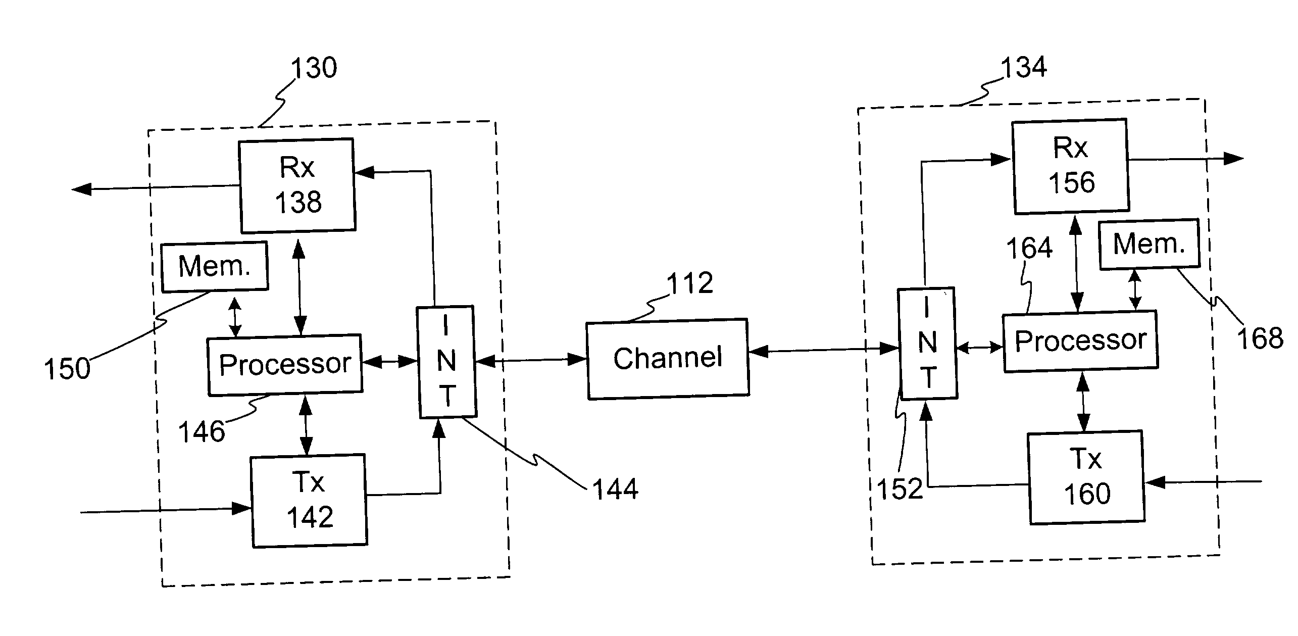
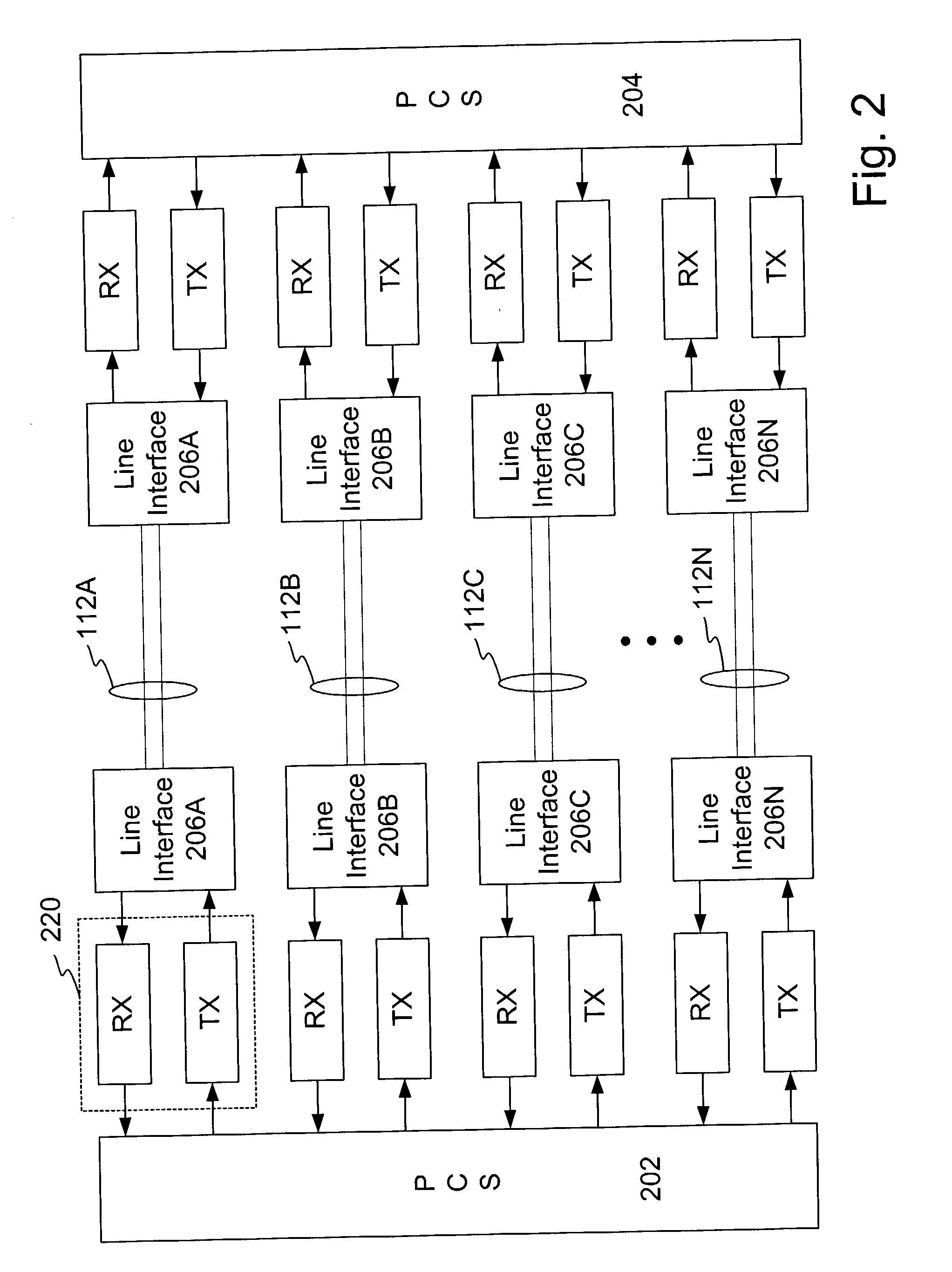
[0108] FIG. 12 illustrates a block diagram of an example implementation of a receiver. This implementation example is provided for purposes of understanding and not limitation. In one exemplary embodiment the full rate input data stream provided to the de-multiplexer 1204 is a twelve bit wide word presented at a rate of 10 / 12 GHz. The data / control type input 1202 is also shown. The term control type is defined to mean a value that indicates whether the current input is a control symbol and, if so, uniquely identifies the type of control word at the input. The de-multiplexer 1204 output is a fractional rate data stream and in this implementation example comprises 4 sets of twelve bit words at a rate of 10 / 48 GHz. This data stream is provided as an input to 4 forward error correction (FEC) encoders 1208 that comprises an 8-state Ungerboeck trellis encoder 1208. The output of the encoder 1208 comprises a fractional rate encoded data stream.

[0109] In the implementation example discussed...


PUM


Abstract

A method and apparatus is disclosed for facilitating high-speed data communication. In one embodiment a receiver is configured to include error correction coding in an interleaved environment to increase data transmission rates. In one embodiment the signal mapping scheme includes constellation shaping to reduce transmit power levels. In one embodiment 8-state Ungerboeck trellis coding is implemented with 4-dimensional PAM10 signal mapping.

Description

1. FIELD OF THE INVENTION[0001] The invention relates to communication systems and in particular to a method and apparatus for data encoding and decoding.2. RELATED ART[0002] Demand for high rate data transmission continues to increase in response to new service offerings and expanded communication network usage, such as for home and business tasks. For example, audio and video content is growing in popularity and is generally bandwidth intensive. In addition, many tasks are now commonly handled via a computer network, such as ordering business supplies, exchanging documents, and information gathering. Moreover, bandwidth demand placed upon a company's local area network is increasing. Often networks are being burdened with more users and larger and more complex software applications. These applications are bandwidth intensive and the complex software applications create larger files. Although many networks are currently at bandwidth capacity additional demands are continually being...

Claims


Application Information

Patent Timeline
IPC IPC(8): H03M13/25H04L1/00H04L25/03
CPCH03M13/256H04L1/0041H04L25/03343H04L1/0071H04L1/006
Inventor MCCLELLAN, BRETT ANTHONY
Owner MARVELL ASIA PTE LTD
Learn More