
Production of carbon and carbon-based materials

Inactive Publication Date: 2003-12-25
COMMONWEALTH SCI & IND RES ORG
View PDF7 Cites 19 Cited by
  • Summary
  • Abstract
  • Description
  • Claims
  • Application Information

AI Technical Summary

Benefits of technology

[0014] The arc attachment to the anode electrode is preferably controlled by being restricted to a particular region of the electrode, and the arc attachment area to the electrode is preferably minimised.
[0015] The applicants have found that minimising the size of the arc-anode attachment region increases the energy density at the surface of the electrode which results in the production of more precursor material (ions and / or atoms). This advantageously results in a higher rate of production of materials for deposit on a substrate. There is more precursor material and the material components (ions and / or atoms) have higher velocities (because they are more energised), resulting in higher rates of deposition and also enhanced film properties.
[0021] Control of the arc attachment area may also be achieved through varying the arc current. For example, the size of the arc-electrode attachment region may decrease when the arc current increases.
[0022] Control of the arc attachment may also be achieved by increasing the cooling of the electrode. For example, the size of the arc attachment decreases, where the electrode is a rod electrode, if the length of the rod electrode (between where it is held in an electrode holder and the electrode tip) is decreased.
[0023] Control of the arc attachment to the anode may also be achieved from use of different cathode materials. For example, using copper as a material for the cathode and graphite as a material for the anode (with a rod-like anode) the arc-anode attachment region may be reduced. Using a graphite cathode will cause the arc-anode attachment region to spread over a larger area of the anode surface.
[0029] The control means may control the arc attachment area to minimise the arc attachment area to the anode electrode. It may also be arranged to adjust the arc attachment area to the anode electrode.

Problems solved by technology

Further, usually when a film becomes too thick it may disintegrate into flakes.

Method used


Image

  • Production of carbon and carbon-based materials
  • Production of carbon and carbon-based materials
  • Production of carbon and carbon-based materials

Examples


Embodiment Construction

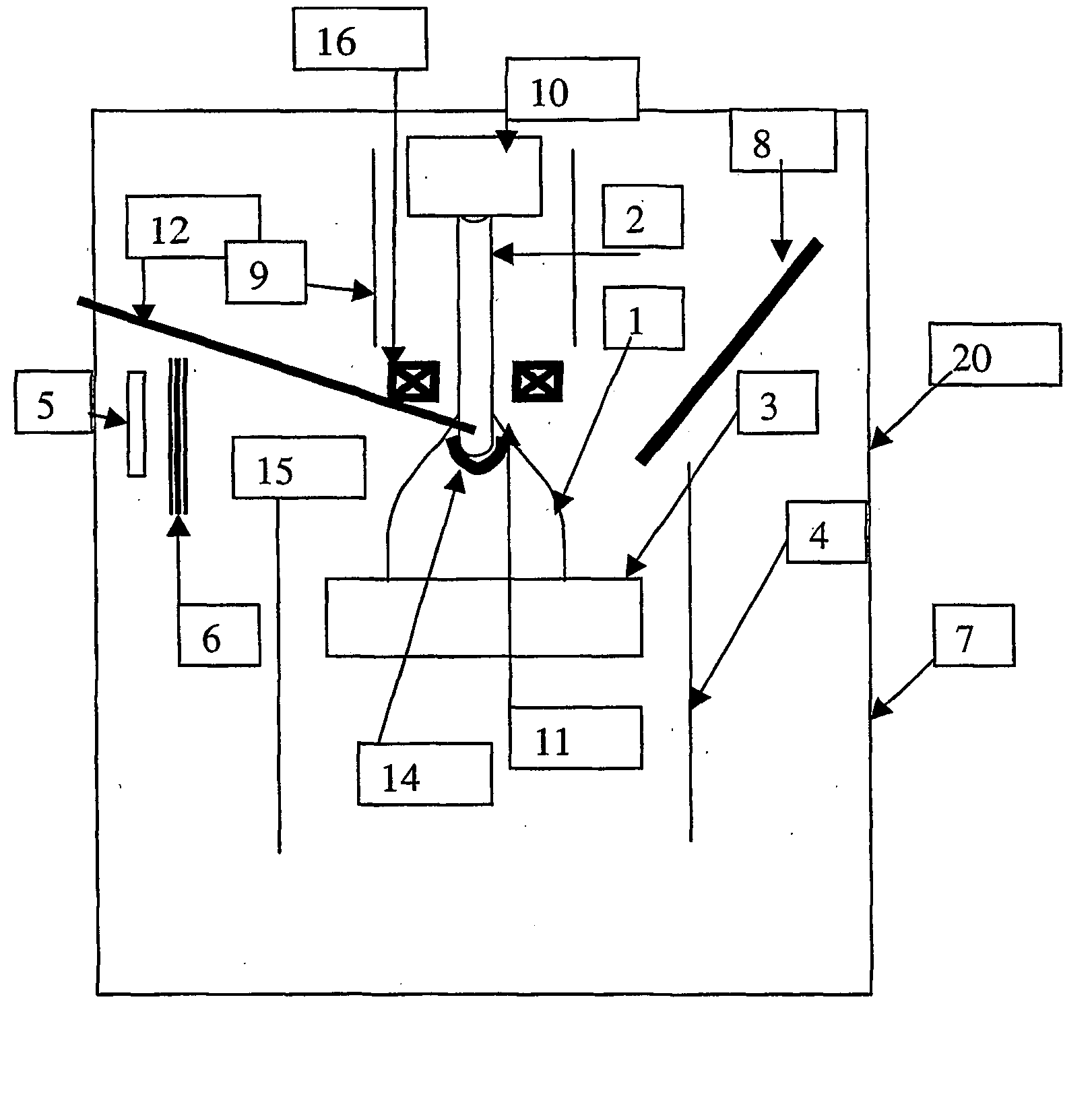
[0056] Referring to the drawing, an arc system, generally designated by reference numeral 20, is shown, for producing carbon or carbon-based material for depositing on a substrate. In this embodiment, the substrate is an object 5. The object 5 may be any object on which it is desired to deposit a carbon film or carbon-based film, in order to provide it with specific properties, e.g. conductivity, hardness, a low friction surface, roughness.

[0057] The arc system 20 includes an electrode 2, from which a carbon based coating precursor material or carbon coating precursor material is produced when an arc 1 is applied to the electrode 2. In this embodiment, the electrode 2 is a graphite anode.

[0058] A control means for controlling an arc attachment area, (indicated by curved line 14), to the electrode 2 is also provided. The control means in this embodiment includes a movable shield 9 (of boron nitrate), the composition of the material of the electrode 2 and also a magnetic coil 16.

[0059...


PUM

PropertyMeasurementUnit
Compositionaaaaaaaaaa
Magnetic fieldaaaaaaaaaa
Currentaaaaaaaaaa

Abstract

The present invention relates to the depositing of carbon and carbon-based materials to produce hard carbon films or carbon-based films. The present methods for producing carbon films and carbon-based films include chemical vapour deposition and filtered arc systems. Both have problems. The present invention discloses a method and apparatus which utilises an arc system comprising an anode and a cathode both of graphite. The graphite anode is used to produce the carbon or carbon-based film precursor material. In order to control the quality and rate of deposition of the precursor material onto a substrate, the arc attachment area to the anode is controlled. Minimising the arc attachment area can increase the rate of deposition.

Description

[0001] The present invention relates to the production of carbon and carbon-based materials, and, particularly, but not exclusively, to a method and apparatus for deposition of hard carbon films and carbon-based films.BACKGROUND OF INVENTION[0002] Hard carbon films and carbon-based films are used in several industrial applications to enhance performance of coated objects. For example, coating objects with a hard carbon film or a metal-carbide film can give improved resistance to wear. These films may have extreme hardness and a very low coefficient of friction. The films may also have enhanced field emission characteristics so they can be used with such products as field emission cathodes in flat panel displays.[0003] Existing technologies for depositing hard carbon films include chemical vapour deposition (CVD) processes and filtered arc systems.[0004] The CVD process uses a low pressure, low current electrical discharge. In CVD systems, chemical compounds containing the carbon to ...

Claims


Application Information

Patent Timeline
IPC IPC(8): C01B31/02C23C14/06C23C14/32C23C16/50C23C26/00
CPCC23C14/325C23C14/0605
Inventor HAIDAR, JAWAD
Owner COMMONWEALTH SCI & IND RES ORG
Learn More