Compressor device and control method for the same
a compressor and compressor technology, applied in the direction of machines/engines, positive displacement liquid engines, lighting and heating apparatus, etc., can solve the problems of engine stall, difficult to accurately control the displacement of the compressor by the pressure control valve, and compressor operation torque may become larger than engine torqu
- Summary
- Abstract
- Description
- Claims
- Application Information
AI Technical Summary
Benefits of technology
Problems solved by technology
Method used
Image

Examples
first embodiment
[0032] (First Embodiment)
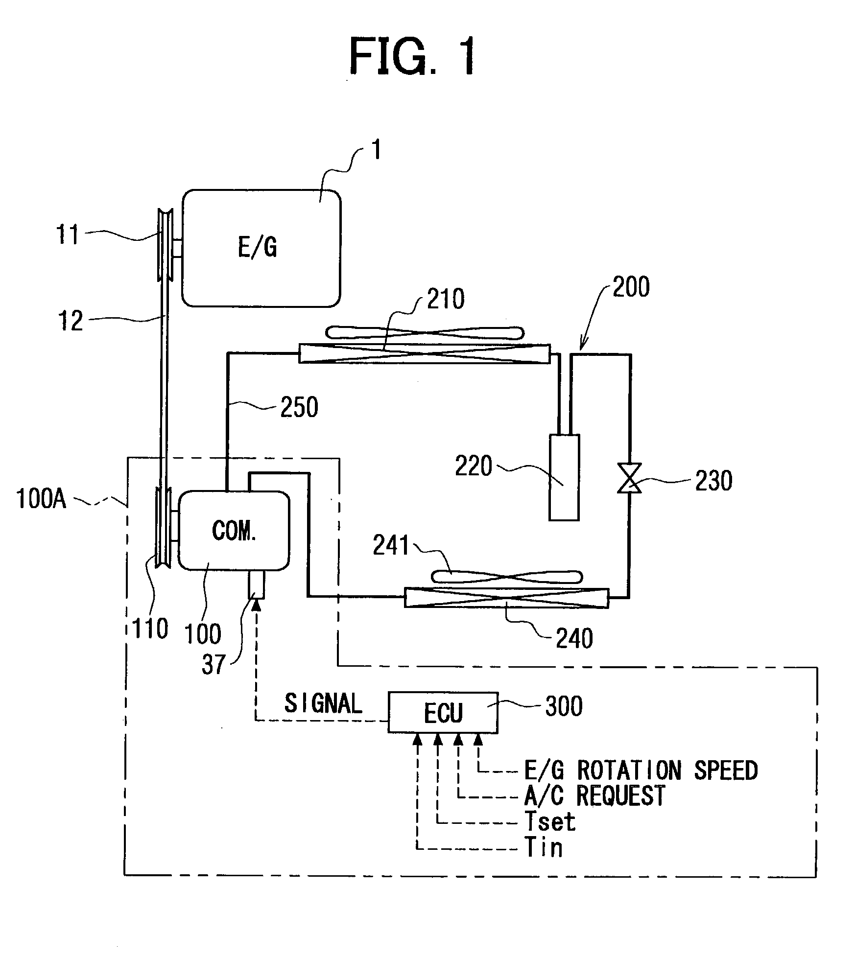
[0033] The first embodiment of the present invention will be now described with reference to FIGS. 1-6. As shown in FIG. 1, a compressor device 100A of the first embodiment includes a compressor 100 and a control unit (ECU) 300. The compressor 100 is provided in a refrigerant cycle system 200 of a vehicle. Further, the compressor 100 is operated by motive power from a vehicle engine (E / G) 1A, and compresses refrigerant in the refrigerant cycle system 200 to a high temperature and high pressure. The refrigerant cycle system 200 includes the compressor 100, a condenser 210, a receiver 220, an expansion valve 230 and an evaporator 240 which are connected by refrigerant piping 250 in this order. The condenser 210 cools and condenses refrigerant compressed by the compressor 100, and the receiver 220 separates the condensed refrigerant from the condenser 210 into gas refrigerant and liquid refrigerant. The expansion valve 230 adiabatically expands and decompresses...
second embodiment
[0058] (Second Embodiment)
[0059] In the above-described first embodiment of the present invention, the upper limit of the current value Cv is set linearly between .alpha.1 (%) and 100 (%) in the rotational speed range of the engine between the idling speed and the predetermined rotational speed A. Similarly, in the second embodiment, the upper limit of the current value Cv is set between .alpha.1% and 100% when the rotational speed R of the engine 1 is lower than the predetermined rotational speed A. However, in the second embodiment, the upper limit of the current value Cv is stepwise changed therebetween as shown in FIG. 7, so that the control program shown in FIG. 5 is made simple. Here, in accordance with output characteristics of the engine 1, the upper limit of the current value Cv can be set at a constant value, in the rotational speed range between the idling rotational speed and the predetermined rotational speed A as shown in FIG. 8. For example, the constant value of the ...
third embodiment
[0060] (Third Embodiment)
[0061] The third embodiment of the present invention will be now described with reference to FIGS. 10 and 11.
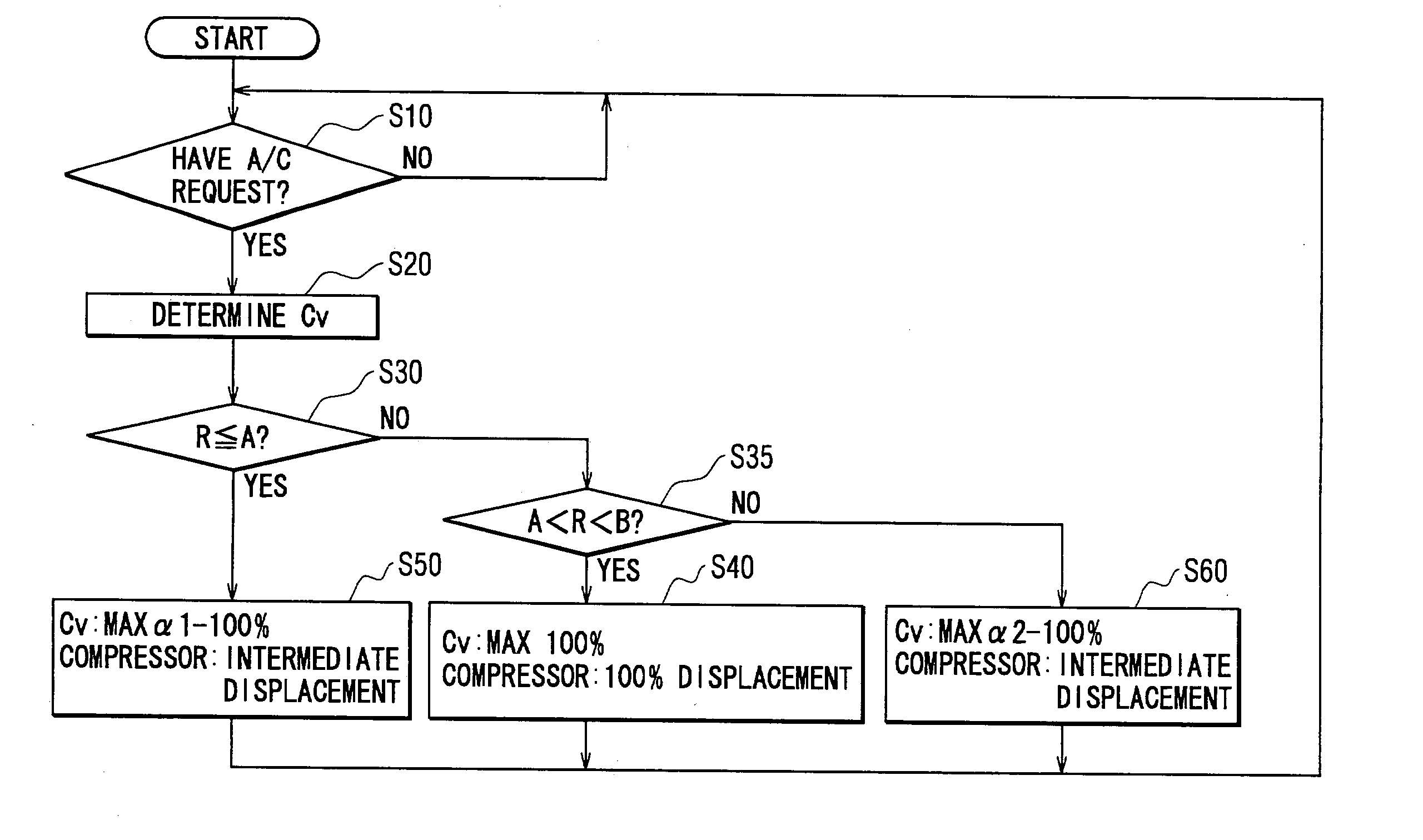
[0062] As shown in FIG. 10, in the third embodiment, a first predetermined rotational speed A similar to the above-described predetermined rotational speed of the first embodiment, and a second predetermined rotational speed B higher than the first predetermined rotational speed A are used. When the rotational speed R of the engine 1 becomes equal to or higher than the second predetermined rotational speed B, the upper limit of the current value Cv is linearly controlled between a second variable maximum value .alpha.2 (%) and maximum 100 (%). The second predetermined rotational speed B is set as a threshold for defining a rotational speed area where the rotational speed R of the engine 1 is controlled mainly based on its output power. Specifically, as shown in FIG. 11, the control operation of the control unit 300 is performed for controlling the dis...
PUM
 Abstract
Description
Claims
Application Information
 - R&D
- Intellectual Property
- Life Sciences
- Materials
- Tech Scout
- Unparalleled Data Quality
- Higher Quality Content
- 60% Fewer Hallucinations
Browse by: Latest US Patents, China's latest patents, Technical Efficacy Thesaurus, Application Domain, Technology Topic, Popular Technical Reports.
© 2025 PatSnap. All rights reserved.Legal|Privacy policy|Modern Slavery Act Transparency Statement|Sitemap|About US| Contact US: help@patsnap.com