Ball valve

A ball valve and valve body technology, applied in the direction of valve details, valve device, valve operation/release device, etc., can solve the problems of shortening the service life of the ball valve, wear of the transmission mechanism, and increasing the difficulty of operation, so as to improve the service life and reduce the operation Torque and friction reduction effect

Pending Publication Date: 2020-07-24
陈少同
View PDF0 Cites 5 Cited by
  • Summary
  • Abstract
  • Description
  • Claims
  • Application Information

AI Technical Summary

Problems solved by technology

[0003] (1) In order to ensure that no internal leakage occurs in the existing ball valve, the ball, that is, the closing part, must be pressed tightly on the valve seat during installation. The torque is large when opening and closing. Severe friction and wear can easily cause leakage, which reduces the reliability of the ball valve and shortens the service life of the ball valve;
[0004] (2) The ball valve of the prior art cannot realize throttling and flow control. In order to adjust the flow in the pipeline, it is also necessary to add a flow regulating valve in the pipeline, which increases the configuration cost of the pipeline;
[0005] (3) For ball valves used in high-pressure pipelines, due to the high pipeline pressure, during the final forced sealing operation, the ball core and seals will be under great pressure, requiring a strong operating torque to open and close the ball valve, which not only It increases the difficulty of operation, and also causes serious wear and tear on the transmission mechanism of the ball valve, which significantly affects the service life of the forced sealing ball valve

Method used


Image

  • Ball valve
  • Ball valve
  • Ball valve

Examples


Embodiment Construction

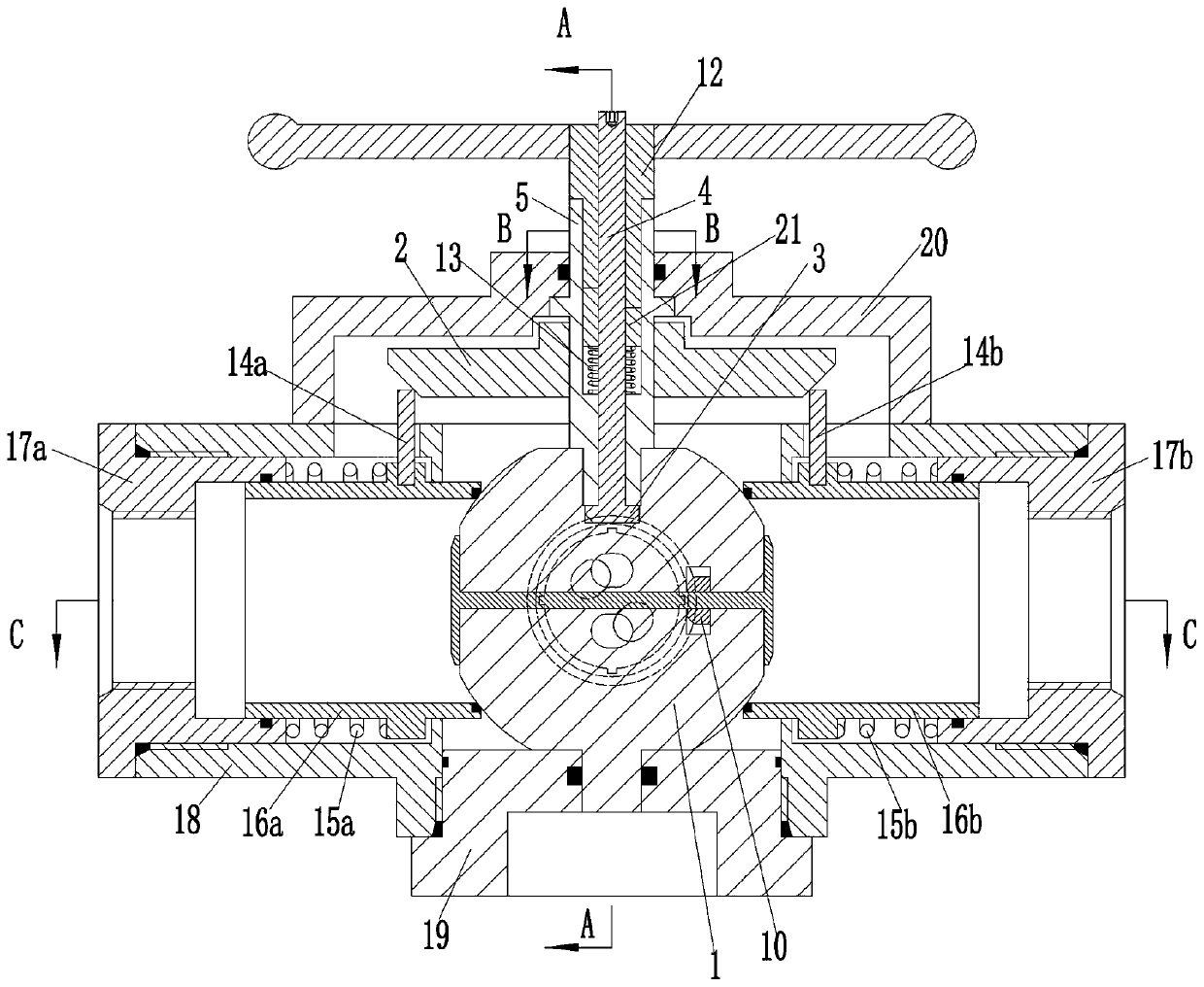
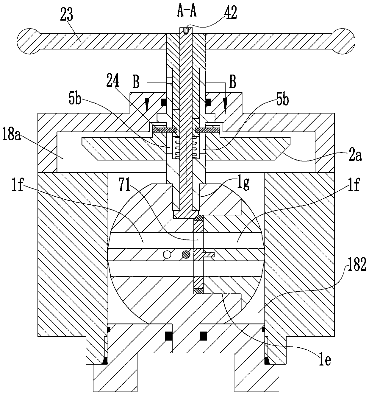
[0041] see Figure 1-15 As shown, a ball valve includes a valve body 18, the valve body 18 is provided with a channel 181 penetrating left and right, and the valve body 18 is provided with a mounting hole 182 along a direction perpendicular to the channel 181, and the valve body 18 is in the An upper end cover 20 is installed on the upper end of the installation hole 182, and a lower end cover 19 is installed on the lower end of the installation hole 182; the lower end cover 19 is rotatably connected with a ball core 1 located in the channel 181, and the ball core 1 is used to control the channel. 181 on and off; the upper end cover 20 is rotatably connected with the valve stem 5 whose lower end is fixedly connected with the ball core 1; an installation cavity 18a is formed between the upper end of the valve body 18 and the upper end cover 20, and the installation cavity 18a is equipped with There is a push plate 2 slidingly connected to the valve stem 5, the side of the push ...


PUM


Abstract

The invention discloses a ball valve. The ball valve comprises a valve body; a channel and a mounting hole are formed in the valve body; an upper end cover is mounted at the upper end of the mountinghole of the valve body; a lower end cover is mounted at the lower end of the mounting hole of the valve body; the lower end cover is rotatably connected with a ball core; the upper end cover is rotatably connected with a valve rod; a mounting cavity is formed between the upper end and the lower end of the valve body; a pushing plate is mounted in the mounting cavity; a left valve seat component isarranged in the valve body; the left valve seat component comprises a left screw sleeve; the interior of the left valve seat component is in sliding connection with a left valve seat cylinder; a leftconvex shoulder is arranged on the outer side wall of the left valve seat cylinder; a left limiting groove is formed in the valve body; a left convex rod is fixedly mounted on the left convex shoulder; a left first spring is arranged between the left screw sleeve and the left convex shoulder; a first tangent plane is formed on the side surface of the ball core; a first shaft hole and a pressure relieving hole are formed in the ball core; the interior of the first shaft hole is rotatably connected with a shaft rod; a first rotating plate is arranged at one end of the shaft rod; the ball valveis not worn in opening and closing processes; and moreover, the torque is small when the ball valve is opened and closed.

Description

technical field [0001] The invention belongs to the technical field of pipeline valves, in particular to a ball valve. Background technique [0002] Pipelines are usually used to transport media in industrial or civil infrastructure, where the pipeline is regulated due to changes in pressure or temperature. In order to adjust the flow, an adjustment mechanism, especially a ball valve, is used in the pipeline to ensure the best work. conditions and environmental safety. Ball valves usually use a sphere with a circular passage as the opening and closing element, and the sphere realizes the opening and closing action with the rotation of the valve body. The opening and closing part of the ball valve is a ball with a through hole, which rotates around the axis perpendicular to the channel, so as to achieve the purpose of opening and closing the channel. A traditional ball valve is usually a sphere with a through hole installed on the valve seat, and the opening and closing are...

Claims


Application Information

Patent Timeline
Patent Type & Authority Applications(China)
IPC IPC(8): F16K5/06F16K5/08F16K5/10F16K5/20F16K31/53F16K31/60
CPCF16K5/0605F16K5/08F16K5/10F16K5/201F16K31/53F16K31/60
Inventor 陈少同姜桂梅马金焕
Owner 陈少同
Why Eureka
Try Eureka