Rolling bearing unit for supporting wheel

a technology of rolling bearing unit and supporting wheel, which is applied in the direction of mechanical equipment, rotary machine parts, transportation and packaging, etc., can solve the problems of troublesome working of inner ring fitting, main body, middle portion, etc., and achieve controllability and durability, the effect of reducing the running torqu

Inactive Publication Date: 2006-07-27
NSK LTD
View PDF2 Cites 5 Cited by
  • Summary
  • Abstract
  • Description
  • Claims
  • Application Information

AI Technical Summary

Benefits of technology

[0041] In contrast, in the case of the present invention, since the torque required to relatively run the stationary side raceway ring and the rotary side raceway ring at 200 min−1 based on the rolling resistance of the balls is regulated in a range of 0.15 to 0.45 N·m, the running torque can be reduced while assuring the controllability and the durability.

Problems solved by technology

A working of fitting the inner ring as the separate body onto the hub main body from the inner end portion to the middle portion while keeping a large inference is troublesome.
Also, in case it is considered only that the sliding resistance of the seal ring is lowered simply, prevention of the entering of the foreign matter into the internal space of the rolling bearing unit cannot be sufficiently attained and thus the durability cannot be sufficiently assured.

Method used


Image

  • Rolling bearing unit for supporting wheel
  • Rolling bearing unit for supporting wheel
  • Rolling bearing unit for supporting wheel

Examples


examples

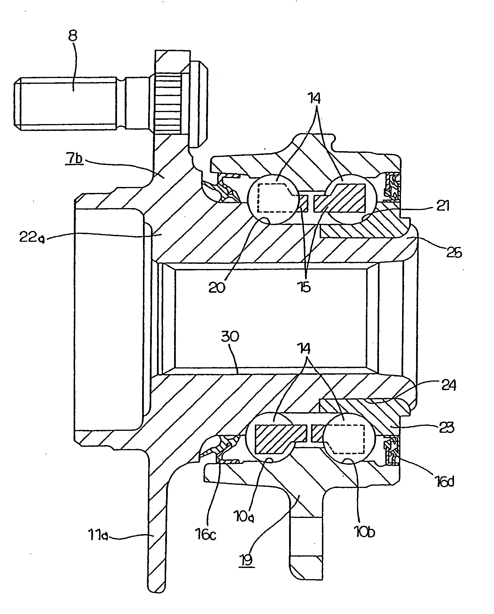
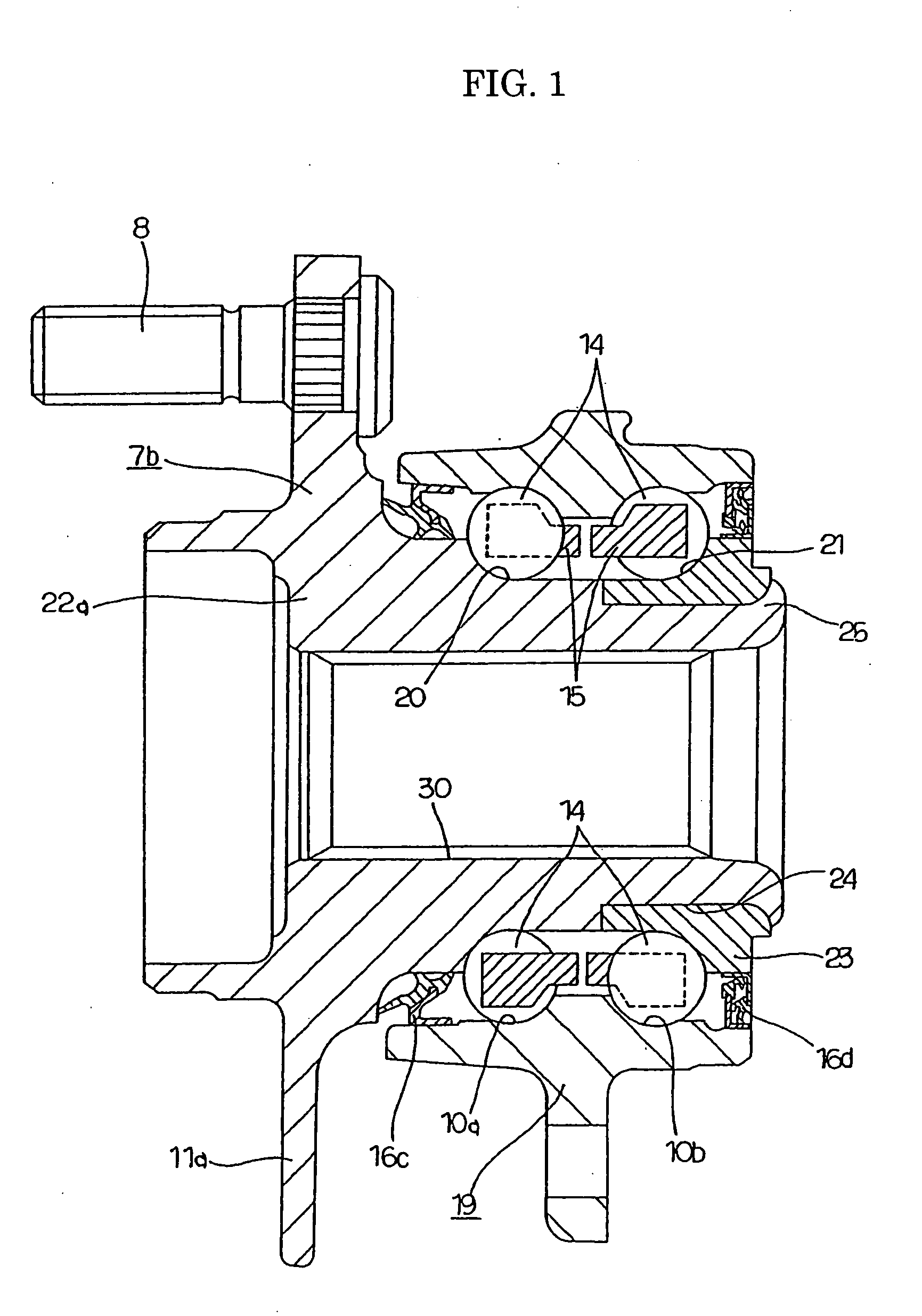
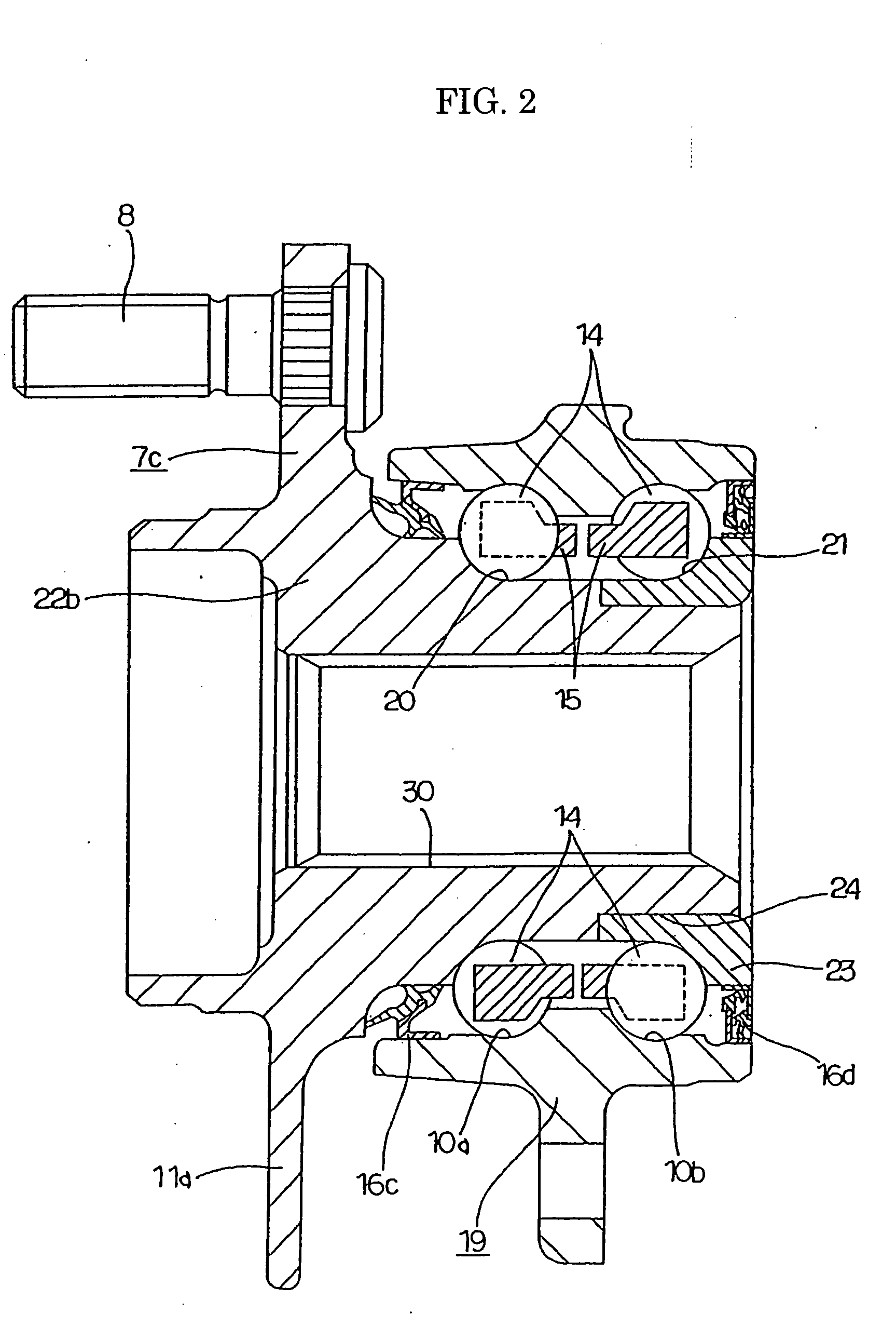
[0075] Next, results of experiments to check advantages of the present invention will be explained hereunder. In Experiment, a pair of seal rings selected from five types of seal rings shown in FIGS. 4 to 8 were assembled into the wheel supporting rolling bearing unit shown in FIG. 1 or FIG. 3, and then the relationship between a total value of the running resistance (seal torque) of both seal rings and the sealing performance was obtained. Adjustment of the sealing torque was executed by adjustment of the interference (an amount of elastic deformation) of the seal lip, adjustment of the thickness of the seal lip, exchange of the elastic material, and adjustment of the contact conditions to the counter surface. Then, six types of seal rings whose seal torque is 0.01 to 0.10 N·m were manufactured with respect to above five types of seal rings respectively. Then, respective seal rings were incorporated into the wheel supporting rolling bearing unit shown in FIG. 1 or FIG. 3 to take a ...


PUM


Abstract

In a wheel supporting rolling bearing unit, both end openings of a space in which balls 14, 14 are provided are sealed with seal rings 16c, 16d each having two to three seal lips. A rolling resistance that changes based on a preload is regulated in a range of 0.15 to 0.45 N·m, and a total running resistance of both seal rings 16c, 16d based on a friction between the seal lips and counter surfaces is regulated in a range of 0.06 to 0.4 N·m.

Description

TECHNICAL FIELD [0001] The present invention relates to improvement in a wheel supporting rolling bearing unit for supporting rotatably a wheel on a suspension system of a vehicle (car). BACKGROUND ART [0002] As the wheel supporting rolling bearing unit, structures shown in FIGS. 10 and 11 are set forth in JP-A-2001-221243, for example. First, a structure of a first example shown in FIG. 10 will be explained hereunder. A wheel 1 constituting the wheel is supported rotatably on an end portion of an axle 3 constituting a suspension system by a wheel supporting rolling bearing unit 2. More particularly, inner rings 5, 5 as a stationary side raceway ring, which constitutes the wheel supporting rolling bearing unit 2, are fitted onto a supporting shaft 4 fixed to the end portion of the axle 3, and then the inner rings 5, 5 are fixed with a nut 6. Meanwhile, the wheel 1 is coupled / fixed to a hub 7 as a rotary side raceway ring, which constitutes the wheel supporting rolling bearing unit 2...

Claims


Application Information

Patent Timeline
Patent Type & Authority Applications(United States)
IPC IPC(8): F16C13/00B60B27/00F16C19/18F16C33/78F16C43/04
CPCB60B27/00F16C19/186F16C33/78F16C43/04F16C2326/02F16C2240/12F16C19/185F16C25/06F16C19/18B60B35/18
Inventor SAKAMOTO, JUNSHI
Owner NSK LTD
Why Eureka
Try Eureka