Drilling tool and indexable drill bit

a drill bit and drill bit technology, applied in the direction of twist drills, manufacturing tools, cutting inserts, etc., can solve the problems of large cutting force at entering, particularly troubling imbalance of this type, and achieve the effect of reducing the number of drill bits

Active Publication Date: 2003-12-04
SANDVIK INTELLECTUAL PROPERTY AB
View PDF16 Cites 25 Cited by
  • Summary
  • Abstract
  • Description
  • Claims
  • Application Information

AI Technical Summary

Problems solved by technology

This results in the cutting forces becoming large at entering.
The two spaced-apart bits use great force to "clutch" the material in the workpiece, the drill being subjected to large radi...

Method used


Image

  • Drilling tool and indexable drill bit
  • Drilling tool and indexable drill bit
  • Drilling tool and indexable drill bit

Examples


Embodiment Construction

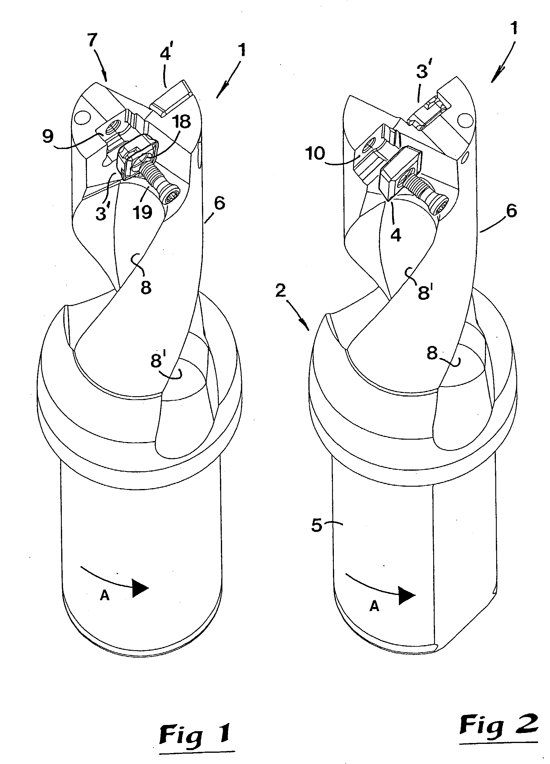
[0024] In FIGS. 1 and 2, a tool in the form of a drill is shown, generally designated 1, which includes a basic body 2 as well as two cutting bits 3', 4'. The basic body 2 is in the example formed with a rear fastening part 5 and a front, long narrow shank 6 of cylindrical basic shape. The length of the shank 6 may vary most considerably. For the sake of clarity, the shank is shown with a limited length. However, in practice, the invention is applicable to drills with considerably longer shanks, e.g. of a length of at least 3.times.D (wherein D equals the diameter of the drill). From the front end or tip, designated 7, in which the bits are arranged, two chip channels 8, 8' extend, which advantageously are helicoidal. Adjacent to the front ends of said chip channels, pockets 9, 10 are formed for receipt of the bits 3', 4'. More precisely, a first pocket 9 is located near the geometrical center axis of the drill for receipt of the bit 3', which constitutes a so-called center bit. The...


PUM

PropertyMeasurementUnit
Fractionaaaaaaaaaa
Fractionaaaaaaaaaa
Fractionaaaaaaaaaa

Abstract

A drilling tool includes a basic body defining a center axis of rotation and having two chip channels and two replaceable indexable cutting bits in the form of a center bit and a periphery bit mounted in respective center and periphery pockets formed in an axially front end of the basic body. The center bit and the center pocket are spaced radially from the periphery bit and the periphery pocket along a first diametrical plane of the basic body. At least the center bit includes four identically-shaped cutting edges, one of which constituting an operative cutting edge intersected by a second diametrical plane oriented perpendicularly to the first diametrical plane. Each cutting edge of the center bit comprises first and second part edges joined by a transition edge portion. The first and second part edges of the operative cutting edge constitutes operative first and second part edges, respectively; the operative first part edge being spaced from the center axis and situated closer than the operative second part edge to an outer periphery of the basic body. An axially forwardmost portion of the operative first part edge is disposed axially forwardly of an axially forwardmost portion of the operative second part edge, and an axially forwardmost portion of an operative cutting edge of the periphery bit lies axially between the axially forwardmost portions of the operative first and second part edges of the center bit, respectively.

Description

[0001] This application claims priority under 35 U.S.C. .sctn..sctn.119 and / or 365 to Patent Application Serial No. 0201587-3 filed in Sweden on May 29, 2002, the entire content of which is hereby incorporated by reference.[0002] In a first aspect, this invention relates to a drill or a drilling tool of the type that comprises on one hand a basic body, which has two chip channels extending rearwards from a front end and is rotatable around a geometrical center axis, and on the other hand two replaceable and indexable bits in the form of a center bit and a periphery bit, which are mounted in pockets formed in the front end of the basic body adjacent to the chip channels. The center bit is mounted in a first pocket or center pocket adjacent to the center axis, and the periphery bit is mounted in a second pocket or periphery pocket adjacent to the periphery of the basic body. The pockets are spaced-apart from each other along a first diametrical plane containing the axis, and the cente...

Claims


Application Information

Patent Timeline
IPC IPC(8): B23B27/14B23B51/00B23B51/04
CPCB23B27/145B23B51/048B23B2200/125B23B2200/201B23B2200/204Y10T408/905Y10T408/9097Y10T408/906Y10T408/90993Y10T407/23Y10S408/713B23B51/00B23B51/02
Inventor ROMAN, STEFANWIDIN, LEIF
Owner SANDVIK INTELLECTUAL PROPERTY AB
Why Eureka
Try Eureka