Methods for making and using point lump-free composions and products coated with point lump-free compositions

Active Publication Date: 2003-11-13
WESTLAKE EPOXY INC
View PDF22 Cites 6 Cited by
  • Summary
  • Abstract
  • Description
  • Claims
  • Application Information

AI Technical Summary

Benefits of technology

[0036] The process may be employed to filter a composition for use as a secondary coating in a wet on wet fiber optic coating process or a wet on dry fiber optic coating process. Preferably, the process may be employed to filter a composition for use as a secondary coating in a wet on wet fiber optic coating process. The present invention selects appropriate temperature, pressure drop and filter pore size to eliminate the gel particles that can cause point lumps.
[0038] Thus, by filtering the coating compositions in accordance with the invention, point lumps, i.e., visible perturbations in the thickness of the primary or secondary coating, or any non-visible deformation resulting in microbending, attentuation or in a decrease in fiber strength can be eliminated.

Problems solved by technology

However, even a small surface flaw can render such a fiber brittle and easily broken.
Specifically, as described in U.S. Pat. No. 4,962,992 to Chapin et al., herein incorporated by reference in its entirety, sub-standard coatings can result in large bubbles, voids, non-concentric coatings and microbending, each of which will often cause transmission errors.
However, the primary coating is not cured until after the secondary coating is applied.
However, coated optical fibers have been known to have imperfect coatings, even with this filtering step.
Generally, imperfections in the coatings may result from process defects (i.e., the process used to coat the glass fibers) or composition defects (i.e., the materials and compositions forming the coatings).
Additionally, defects, such as bubbles or delamination, may be a process defect, a composition defect or combination thereof.
Point lumps may lead to (1) a coated fiber exhibiting a low tensile strength, due mainly to mechanical obstruction in post draw processing (e.g., color inking), or (2) a defect on the coating which can lead to microbending and attenuation.
Additionally, while the presence of point lumps may not reduce the tensile strength of the coated fiber, the point lumps may get caught in a post-process coloring die step.
The presence of point lumps is a problem.
Due to the competitive nature of the optical fiber industry, it is not economical for optical fiber producers to "scrap" or discard product containing such imperfections.
Compounding the problem is the fact that the point lumps are not detectable until after the coatings have been applied to the glass fiber.
Unfortunately, the only known way to test for point lumps is to draw fiber from a preform and coat the drawn fiber.
Even then, no known automatic testing device has been developed for isolating point lumps.
Devices, however, do exist to determine a total number of defects present, as long as certain conditions are met, but the results do not specifically determine the number of point lumps present.
Thus, the testing process is time consuming and expensive.
Additionally, the same types of problems, i.e., the inclusion of point lumps, have been known to cause the same unwanted point lumps in other products requiring a coating, such as compact disks, dental compositions and laminated surfaces.

Method used


Image

  • Methods for making and using point lump-free composions and products coated with point lump-free compositions
  • Methods for making and using point lump-free composions and products coated with point lump-free compositions
  • Methods for making and using point lump-free composions and products coated with point lump-free compositions

Examples


Embodiment Construction

[0053] A. Point Lumps

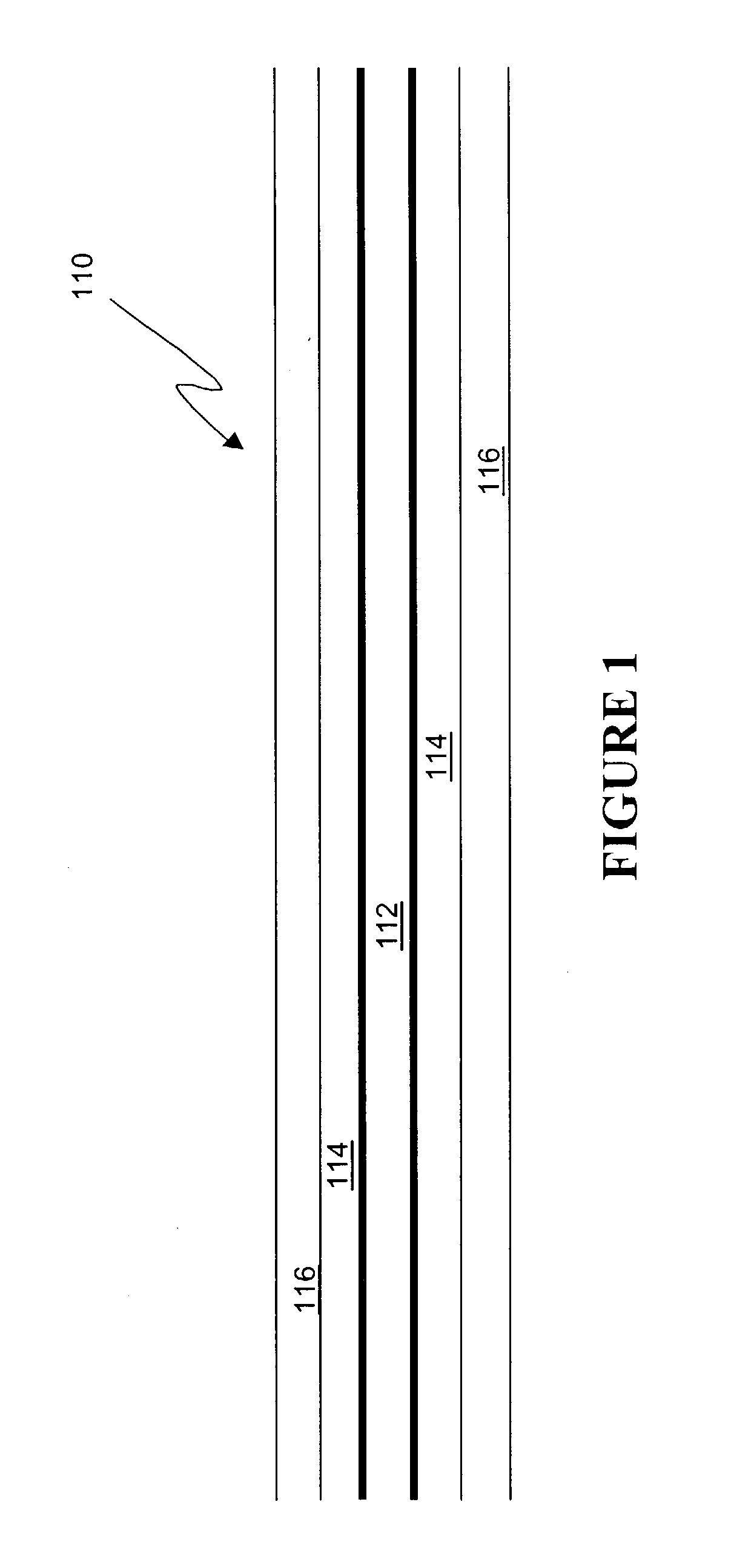
[0054] FIG. 1 shows an optical fiber 110 without any point lumps. In the center of optical fiber 110 is a glass fiber 112, surrounded by a primary coating 114 and a secondary coating 116.

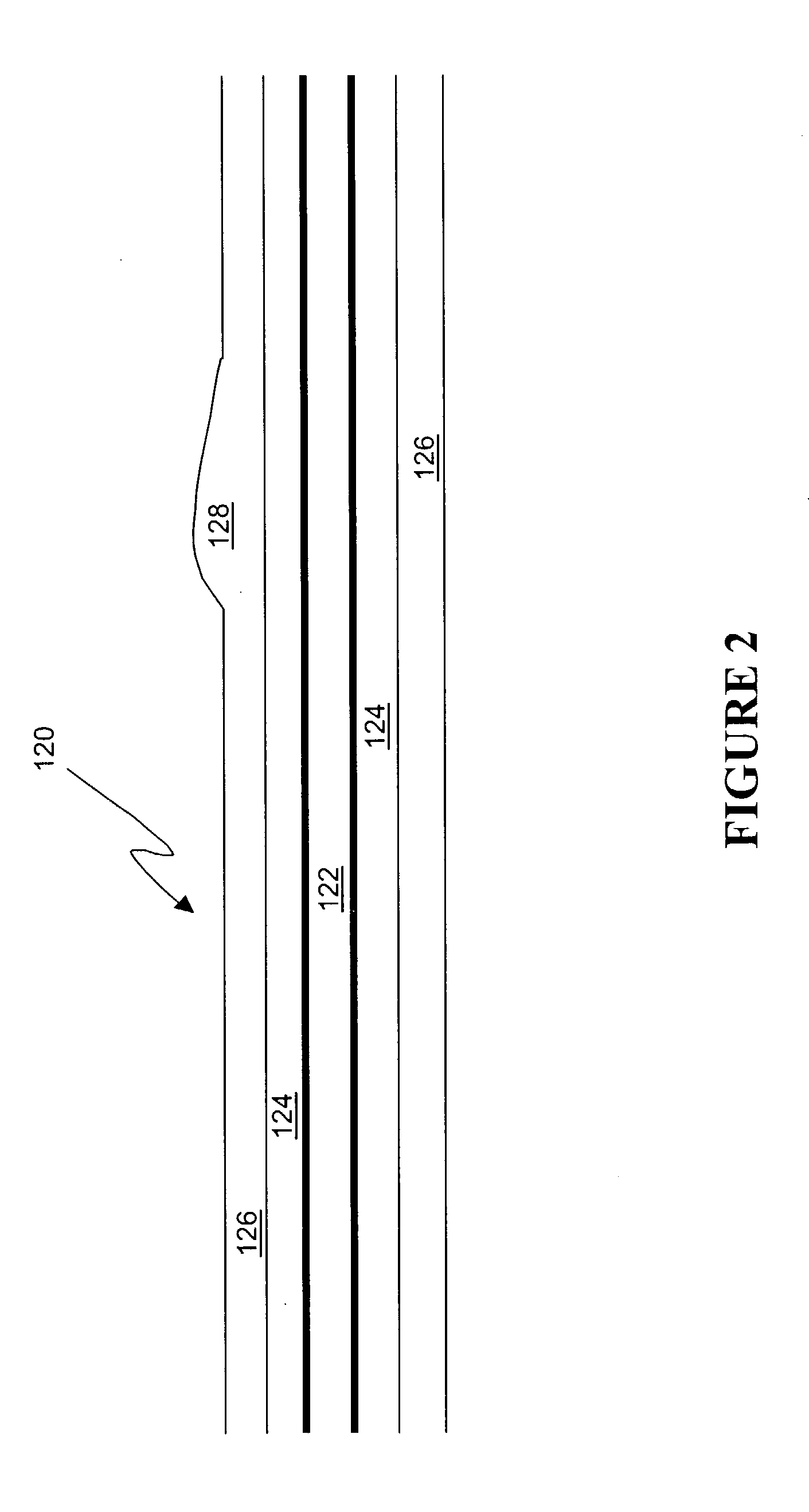
[0055] With reference to FIG. 2, a point lump 128 is shown as a perturbation in or on secondary coating 126. Essentially, point lump 128 is a defect in coatings as applied to the surface of a glass fiber 122, resulting in dislocations in a surface of secondary coating 126. The dislocations resulting from the presence of point lump 128 result in a displacement of the surface of secondary coating 126 approximately 5 microns, as compared to the locations where there is no point lump 128.

[0056] As shown in FIG. 2, external perturbations resulting from external point lump 128 are caused by dislocation of secondary coating 126 extending away from primary coating 124 and glass fiber 122. FIG. 3 indicates an internal point lump 138, resulting from a dislocation of a secondary coating 13...


PUM

PropertyMeasurementUnit
Temperatureaaaaaaaaaa
Lengthaaaaaaaaaa
Fractionaaaaaaaaaa

Abstract

A method is provided to manufacture a coated substrate, such as an optical fiber, without undesirable point lumps. The method filters a coating composition while controlling the filtering temperature, pressure drop across a filtering assembly, and filter pore size to achieve a resulting filtration factor not greater than 250,000 s<-1>. The filtration factor is a function of filtering temperature and pressure drop across the filtering assembly. Typically, the coating composition is filtered by passing the coating composition through one or more filters of the filtering assembly, having an absolute pore size rating in the range from approximately 0.05 to approximately 5 microns, at a temperature less than approximately 105° F. (40° C.), and at a pressure drop DeltaP across the filtering assembly of at most approximately 80 psig, wherein the ratio of pressure drop (mPa) to viscosity (mPa.s), which is dependent upon filtering temperature, minimizes the filtration factor to <=250,000 S<-1>.

Description

[0001] This application claims priority from U.S. Provisional Application No. 60 / 378,663, having a filing date of May 9, 2002, hereby incorporated by reference in its entiretyI. BACKGROUND OF THE INVENTION[0002] A. Field of the Inventions[0003] The present invention relates to the art of coatings for products requiring a substantially clear surface. Specifically, the invention is a solution to the problem of point lumps in the coatings of, for example, optical fibers, by regulating the filtering conditions, such as pore size, pressure drop and temperature during filtering of the coating.[0004] B. Background Discussion[0005] Optical fibers for light transmission as drawn are exceptionally strong and have very few intrinsic defects. However, even a small surface flaw can render such a fiber brittle and easily broken. Thus, such fibers are generally coated by a primary and optionally a secondary coating for protection as disclosed by U.S. Pat. Nos. 6,014,488, 5,352,712, 5,527,835, 5,53...

Claims


Application Information

Patent Timeline
IPC IPC(8): B01D61/14B01D63/14B01D71/34G02B6/44B01D71/56B05D3/00C03C25/12D06M15/564
CPCC03C25/12B05D3/00
Inventor WORKMAN, GREGORY LEE IIKING, DONALD LEONRECHEL, CAMILLE JEANETTEMYERS, TIMOTHY EDWARD
Owner WESTLAKE EPOXY INC
Why Eureka
Try Eureka