
Membrane composite structure and method of production

a composite structure and membrane technology, applied in the field of membrane structure and method of production, can solve the problems of negating the waterproof nature of such a membrane and no longer preventing water passage through the membrane, and achieve the effect of broadening the temperature range of performance and cost-effectiveness

Inactive Publication Date: 2003-10-16
BHA TECH
View PDF24 Cites 21 Cited by
  • Summary
  • Abstract
  • Description
  • Claims
  • Application Information

AI Technical Summary

Benefits of technology

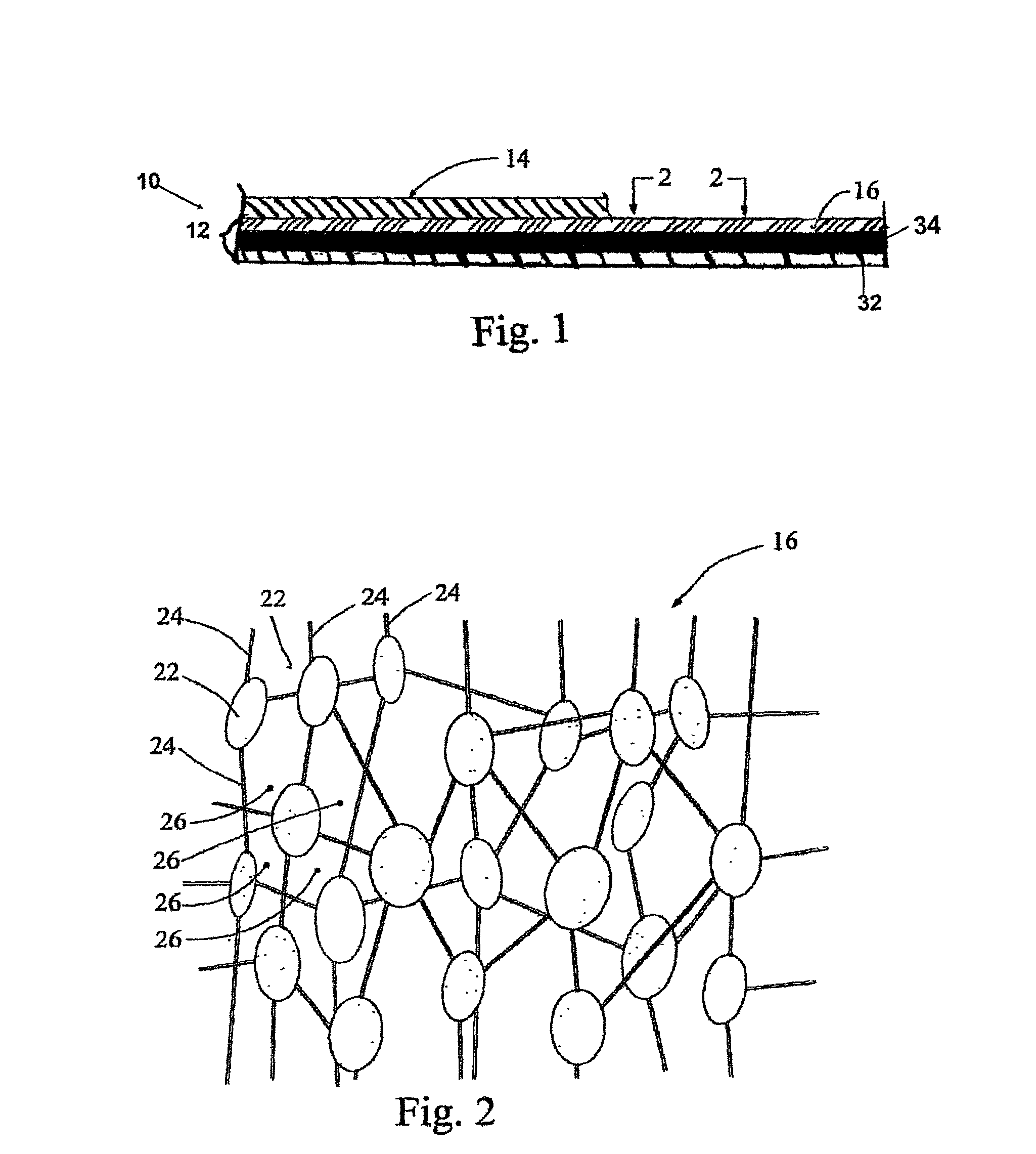
[0014] "Moisture vapor transmissive" is defined as being able to readily permit passage of water vapor through the composite structure 12 as well as the entire laminated fabric 10. The composite structure 12 is preferably "oleophobic", which means that the composite structure 12 is resistant to contamination by absorbing oils, greases or body fluids, such as perspiration and certain contaminating agents. The term "resistant to moisture" is used to described how the composite structure 12 will not "wet" or "wet-out" by a challenge liquid, such as water, and prevents the penetration of liquid through the composite structure 12 under varying ambient conditions of relatively low pressure.
[0030] For all embodiments, the composite structure 12 is preferably, but not necessarily, put through standard rewind station for a textile web (not shown) to reverse the position of the membrane 16 and the thermoplastic material 32. This present invention provides a cost-effective alternative to coating or adhesive lamination of the thermoplastic material 32 to the membrane 16. In addition, this present invention significantly broadens the temperature range of performance. For example, the ePTFE material operates as a scaffold that extends the temperature performance range of pure thermoplastic films from -40 degrees Celsius (-40 degrees Fahrenheit) to -6.67 degrees Celsius (+20 degrees Fahrenheit) above the melting temperature of the pure thermoplastic film.

Problems solved by technology

A significant drawback to the tremendous potential of this material is that body oils, sweat, suntan lotion, and makeup can contact and "foul" portions of the membrane and create areas that no longer prevent water passage through the membrane and thereby negate the waterproof nature of such a membrane.

Method used


Image

  • Membrane composite structure and method of production
  • Membrane composite structure and method of production
  • Membrane composite structure and method of production

Examples


Embodiment Construction

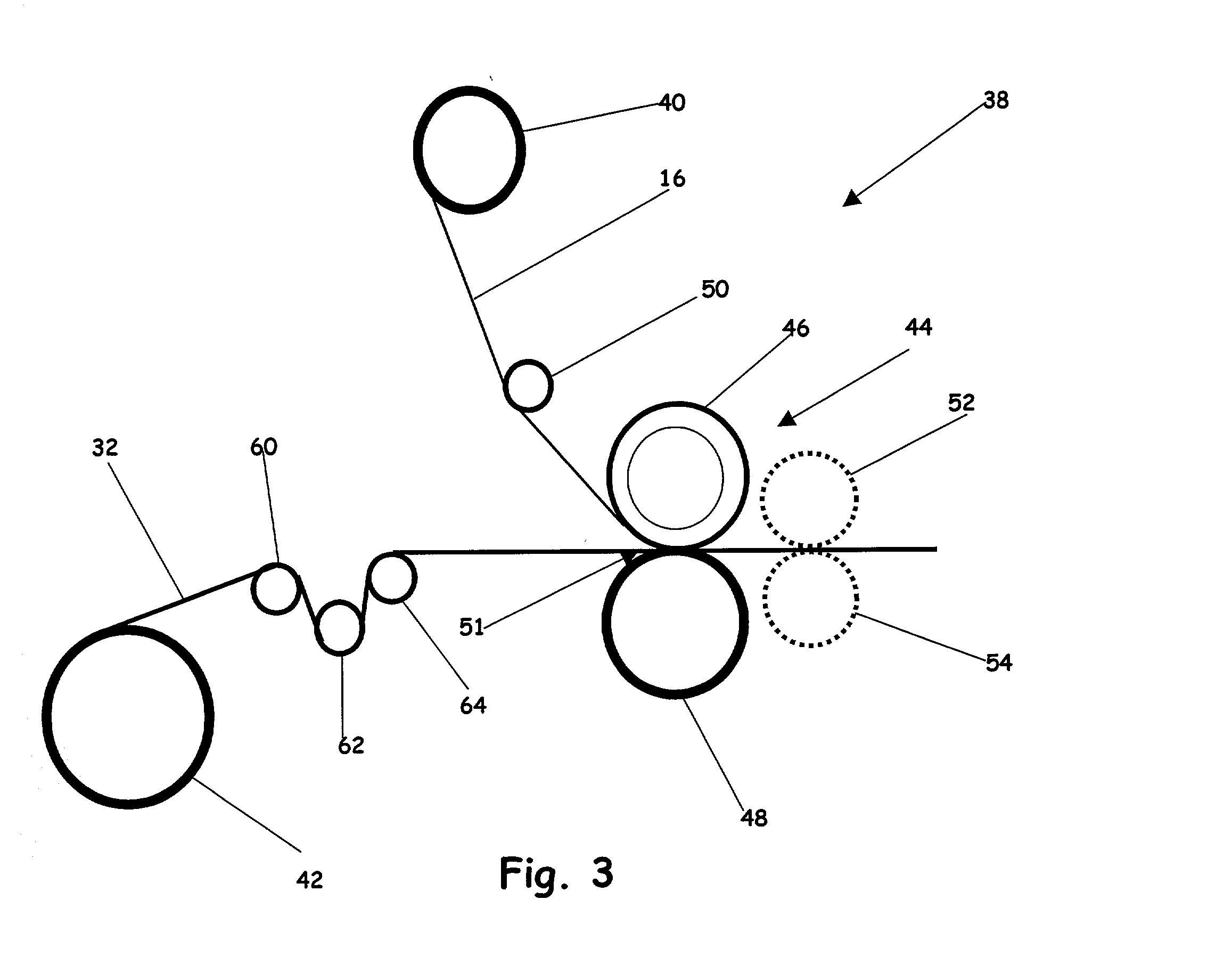
[0037] Utilizing the previously described melting system 38 that utilizes a hot roll calendering mechanism 44 that includes a heated roll 46 and a water-cooled, compression roll 48, which are separated by the gap 51, for applying heat to the membrane 16 and pressure to the membrane 16 and the thermoplastic material 32 in order to create melted thermoplastic material 34 that flows around at least one structural element, e.g., node or fibril, of the plurality of structural elements, e.g., nodes and fibrils, of the membrane 16 to provide attachment when the thermoplastic material 34 again solidifies by capturing the at least one structural element, e.g., node or fibril, of the plurality of structural elements, e.g., nodes and fibrils, of the membrane to attach the first layer 16 and the second layer 32 together to form the resulting composite structure 12. In this example, the membrane 16 is ePTFE and the thermoplastic material 32 is polyurethane. The illustrative, but nonlimiting, par...


PUM

PropertyMeasurementUnit
sizeaaaaaaaaaa
sizeaaaaaaaaaa
melting temperatureaaaaaaaaaa

Abstract

A composite structure (<bold>12< / highlight>) that includes a first layer that includes a membrane (<bold>16< / highlight>) having a first melting point and a plurality of structural elements and a second layer that includes a thermoplastic material (<bold>32< / highlight>) having a second melting point that is lower than the first melting point, wherein at least a portion of the thermoplastic material (<bold>34< / highlight>) is at least one partially melted to flow around at least one structural element of the plurality of structural elements of the membrane (<bold>16< / highlight>) prior to resolidification to attach the first layer (<bold>16< / highlight>) to the second layer (<bold>32< / highlight>). The membrane (<bold>16< / highlight>) can be oleophobic or oleophilic and preferably includes expanded polytetrafluoroethylene. The thermoplastic material (<bold>32< / highlight>) can be of virtually any type and can be either hydrophobic or hydrophilic.

Description

[0001] This invention relates to a composite structure, and more particularly, to an improved composite structure that utilizes a thermoplastic material that is thermally melted to a porous membrane and a method of production.[0002] A membrane, such as an expanded polytetrafluoroethylene (ePTFE) membrane, provides a significant advantage of being porous. This allows perspiration and moisture vapor to pass directly through the membrane while remaining waterproof. A significant drawback to the tremendous potential of this material is that body oils, sweat, suntan lotion, and makeup can contact and "foul" portions of the membrane and create areas that no longer prevent water passage through the membrane and thereby negate the waterproof nature of such a membrane.[0003] The present invention is directed to overcoming the drawback set forth above.SUMMARY OF INVENTION[0004] In one aspect of this invention, a composite structure is disclosed. This composite structure includes at least one ...

Claims


Application Information

Patent Timeline
Patent Type & Authority Applications(United States)
IPC IPC(8): B01D69/10B01D71/36B29C65/14B29C65/18B32B27/04B32B37/20B32B38/00
CPCB01D69/10B29C66/727B29C65/1412B29C65/1432B29C65/1467B29C65/18B29C66/45B29C66/81811B29C66/83413B29C66/83417B29K2027/18B29L2009/00B32B27/04B32B37/04B32B37/203B32B38/0036B32B2305/026B32B2305/18B32B2307/724B32B2307/7265B32B2327/18B01D71/36B29C66/8181B29C65/1445B29C65/00B29C66/71B29C66/7392B29C66/73921B29C66/72343B29C66/1122Y10T428/249955Y10T428/249953Y10T442/3886Y10T442/2238Y10T442/2139Y10T442/387Y10T442/2221Y10T428/249958Y10T442/3854B29K2077/00B29K2023/04B29K2023/10B29K2025/04B29K2075/00B29K2067/00B29K2081/06B29K2071/00B29K2033/12B29K2033/08B29K2025/06B29K2023/12B29K2023/06B29K2023/00B29K2001/00
Inventor FUHRMANN, LOUIS P.TRIMBLE, TIMPILLAI, RAJ
Owner BHA TECH
Learn More