
Thin film magnetic head, method of manufacturing the same and magnetic recording apparatus

Active Publication Date: 2003-10-09
TDK CORPARATION +1
View PDF1 Cites 18 Cited by
  • Summary
  • Abstract
  • Description
  • Claims
  • Application Information

AI Technical Summary

Benefits of technology

[0013] Moreover, it is a second object of the invention to provide a method of manufacturing a thin film magnetic head capable of achieving compatibility between the highly accurate formation of a main pole layer and proper positioning of a flare point so as to contribute an improvement in the recording performance in the viewpoint of manufacturing.
[0014] Further, it is a third object of the invention to provide a magnetic recording apparatus capable of improving recording performance.

Problems solved by technology

However, conventional methods of manufacturing a thin film magnetic head has such a problem that in spite of the fact that highly accurate formation of the uniform width portion and proper positioning of a flare point are required in order to improve the recording performance, it is difficult for them to be compatible.
When the exposed region is expanded, the forming accuracy of the photoresist pattern declines, so it is difficult to form the uniform width portion with high accuracy.
Further, as the flare point comes closer to the air bearing surface, thereby a ratio of the region with the wide width to the region with the minute width increases, a problem with the forming accuracy of the uniform width portion becomes more pronounced.
However, no specific way to achieve the compatibility between the highly accurate formation of the main pole layer and proper positioning of the flare point has been indicated in the related art.

Method used


Image

  • Thin film magnetic head, method of manufacturing the same and magnetic recording apparatus
  • Thin film magnetic head, method of manufacturing the same and magnetic recording apparatus
  • Thin film magnetic head, method of manufacturing the same and magnetic recording apparatus

Examples


Embodiment Construction

[0143] Next, a result of an experiment for determining various properties of the thin film magnetic head according to the invention will be described below.

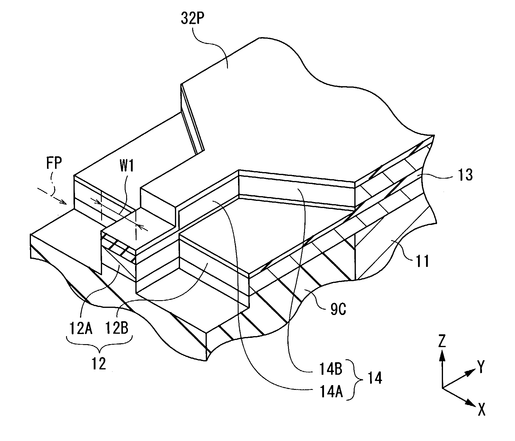
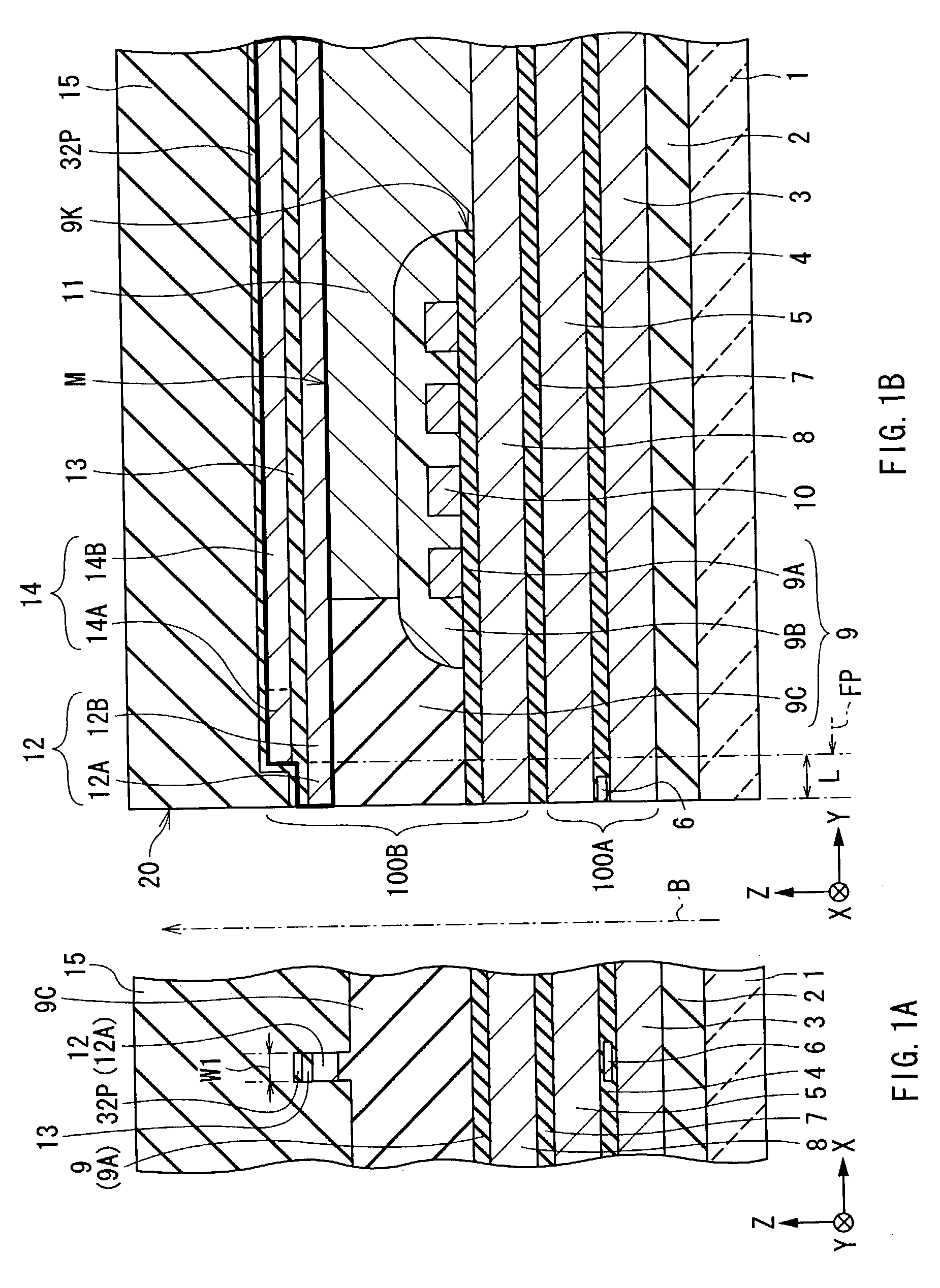
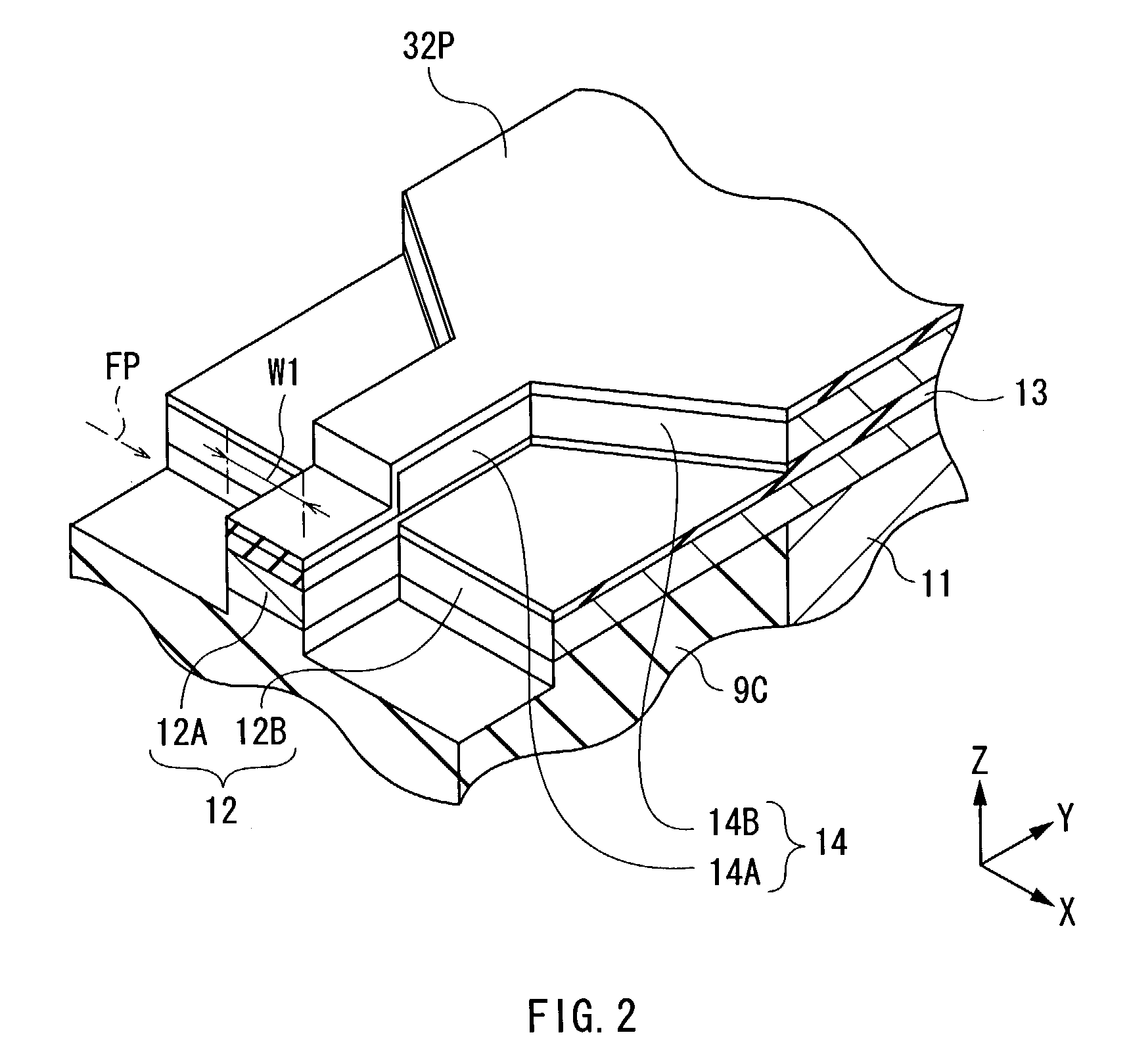
[0144] When the thin film magnetic head comprising the laminate including the main pole layer, the non-magnetic layer and the auxiliary pole layer formed through the method of manufacturing the thin film magnetic head according to the invention was manufactured so as to determine the properties thereof, a result shown in FIG. 32 was obtained. FIG. 32 shows an advantage of the thin film magnetic head and the method of manufacturing the same according to the invention, and a "lateral axis" indicates the recessed distance L (.mu.m), and a "vertical axis" indicates an overwrite (O.W.) property (dB; ".quadrature.") and a standard deviation .sigma. of the processed width W1 of the front end portion (.mu.m; ".diamond-solid."). Moreover, in order to compare with the invention, a thin film magnetic head was manufactured through a conventi...


PUM

PropertyMeasurementUnit
Thicknessaaaaaaaaaa
Magnetic fieldaaaaaaaaaa
Widthaaaaaaaaaa

Abstract

Provided is a thin film magnetic head capable of improving recording performance. The thin film magnetic head comprises a laminate including a main pole layer and an auxiliary pole layer being disposed in a region facing the main pole layer with a non-magnetic layer in between. After magnetic flux generated in a thin film coil is contained in the auxiliary pole layer through the non-magnetic layer, and then is concentrated on a front end neighboring portion of a front end portion in the auxiliary pole layer, the magnetic flux passes through the non-magnetic layer again so as to flow into a front end portion of the main pole layer. A "main magnetic flux incoming route" flowing from a rear end portion to the front end portion in the main pole layer and an "auxiliary magnetic flux incoming route" flowing from the auxiliary pole layer to the front end portion of the main pole layer can be obtained, so an amount of the magnetic flux supplied to a portion of the front end portion of the main pole layer on a trailing side increases. As a sufficient amount of the magnetic flux is supplied to a portion of the front end portion of the main pole layer on the trailing side so that an emitting amount of the magnetic flux increases, thereby a generation intensity and a magnetic field gradient of a perpendicular magnetic field can be obtained.

Description

[0001] 1. Field of the Invention[0002] The present invention relates to a thin film magnetic head comprising at least an inductive magnetic transducer for recording, a method of manufacturing the same, and a magnetic recording apparatus such as, for example, a hard disk drive which comprises the thin film magnetic head.[0003] 2. Description of the Related Art[0004] In recent years, an improvement in performance of thin film magnetic heads has been sought in accordance with an increase in the areal density of a magnetic recording medium (hereinafter simply referred to as "recording medium") such as, for example, a hard disk. As magnetic recording systems applicable to thin film magnetic heads, for example, a longitudinal recording system that a signal magnetic field is oriented in an in-plane direction of a recording medium (a longitudinal direction) and a perpendicular recording system that the signal magnetic field is oriented in a direction perpendicular to the recording medium ar...

Claims


Application Information

Patent Timeline
IPC IPC(8): G11B5/00G11B5/012G11B5/127G11B5/31
CPCG11B5/00G11B5/012Y10T29/49032G11B5/313G11B2005/0029G11B5/1278
Inventor MATONO, NAOTOSHOJI, SHIGERU
Owner TDK CORPARATION
Learn More