
Perpendicular magnetic recording head and magnetic recording device

a technology of magnetic recording head and magnetic recording device, which is applied in the field of perpendicular magnetic recording, to achieve the effects of ensuring the magnitude suppressing the spread of the recording magnetic field, and improving the recording performan

Active Publication Date: 2012-10-30
TDK CORPARATION
View PDF24 Cites 16 Cited by
  • Summary
  • Abstract
  • Description
  • Claims
  • Application Information

AI Technical Summary

Benefits of technology

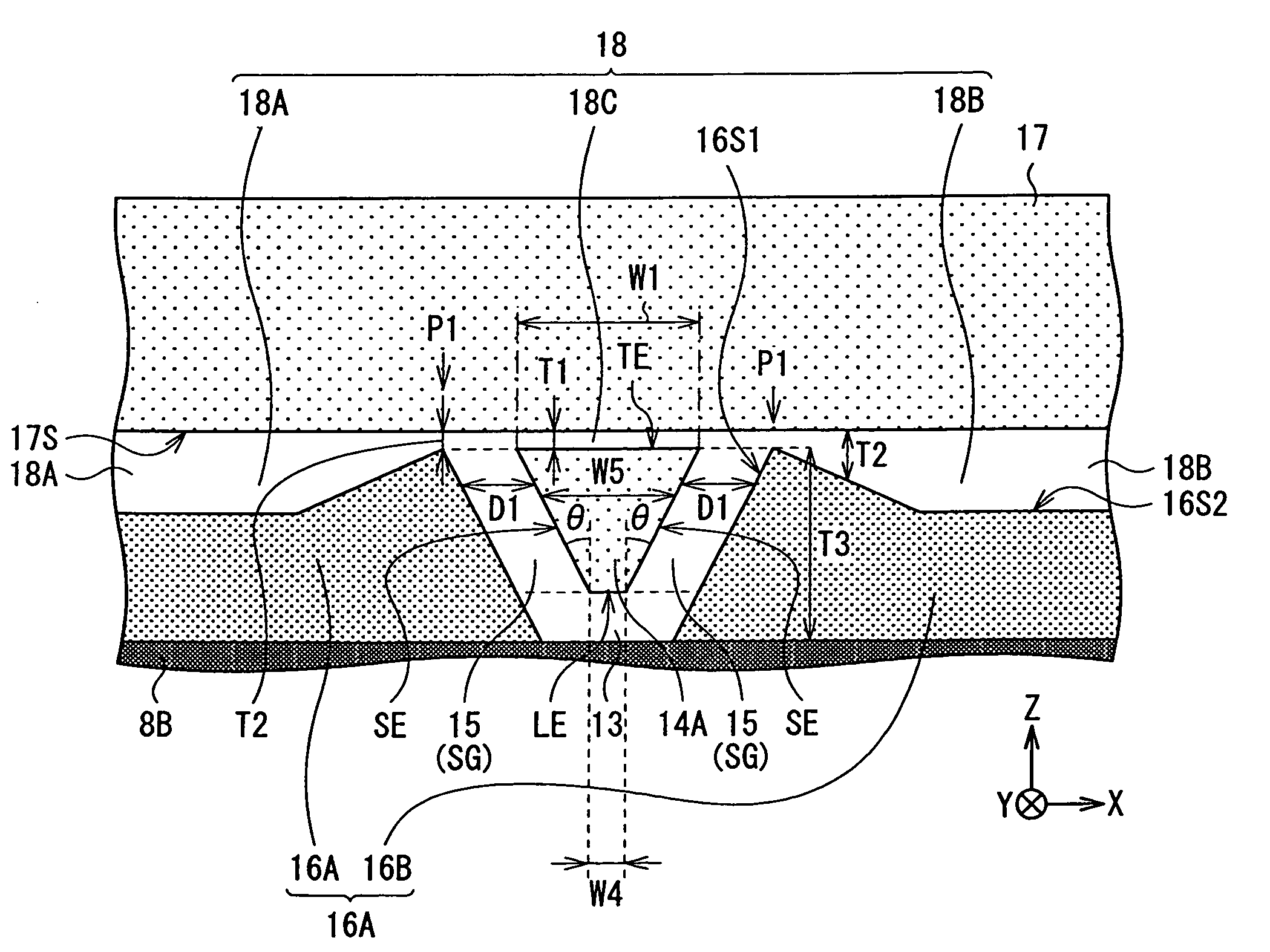
[0011]In the perpendicular magnetic write head and the magnetic recording device, each according to the embodiment of the present invention, the magnetic pole, the pair of side shields, and the trailing shield are mutually separated by the side gap or the trailing gap. Moreover, the overall or a part of the second regional part, which separates the pair of side shields from the trailing shield, has the thickness larger than the thickness of the first regional part, which separates the trailing edge of the magnetic pole from the trailing shield. These make it easier for a spread component of magnetic flux to be absorbed in a portion in the vicinity of the trailing edge in the side shield, and make it less likely for the magnetic flux to be excessively absorbed in a portion except for the portion in the vicinity of the trailing edge in the side shield. As a result, realized are both ensuring a magnitude of a recording magnetic field and suppressing a spread of the recording magnetic field, so that it is possible to improve recording performance.

Problems solved by technology

However, the conventional perpendicular magnetic recording head, provided with the side shield, has a trade-off relationship between ensuring the magnitude of the perpendicular magnetic field and suppressing the spread of the perpendicular magnetic field, and it is difficult to realize both ensuring the magnitude of the perpendicular magnetic field and suppressing the spread of the perpendicular magnetic field, so that there is still room for improvement in recording performance.

Method used


Image

  • Perpendicular magnetic recording head and magnetic recording device
  • Perpendicular magnetic recording head and magnetic recording device
  • Perpendicular magnetic recording head and magnetic recording device

Examples


modification 1

(Modification 1)

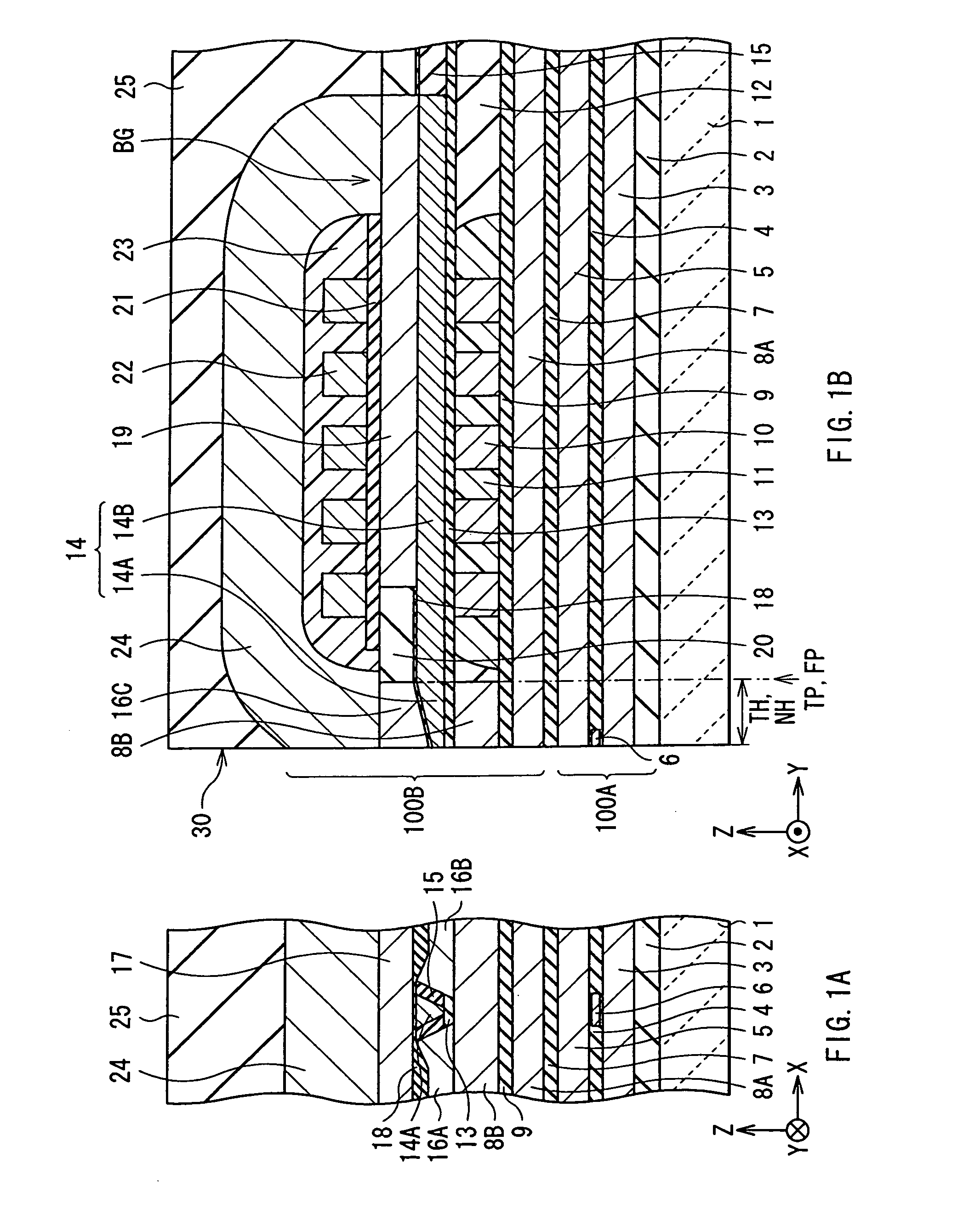
[0110]This modification, as illustrated in FIGS. 23A, 23B, has the configuration in which the leading shield 8B is coupled to the magnetic layer 8A extending rearward from the air bearing surface 30. Here, the thin-film coil 10 is provided so as to penetrate a space surrounded with the leading shield 8B, the magnetic layer 8A, and the main magnetic-pole layer 14. In this modification, it is possible for the recording magnetic field in the vicinity of the trailing edge TE in the thickness direction to have the gradient comparable with the gradient of the thin-film magnetic head in FIG. 4, and further, is possible to decrease the WATE effective magnetic field. This makes it more unlikely to cause the adjacent track erase in a wide range.

modification 2

[Modification 2]

[0111]This modification, as illustrated in FIGS. 24A, 24B, similarly to Modification 1, has the configuration in which the leading shield 8B is coupled to the magnetic layer 8A. Moreover, this modification includes a magnetic layer 8C which extends in the thickness direction toward the rear end portion 14B of the main magnetic-pole layer 14 from a rear end portion in the magnetic layer 8A. The magnetic layer 8C is made of, for example, a constituent material similar to that of the magnetic layer 8A or the leading shield 8B. However, an end portion on the opposite side of the magnetic layer 8A is separated from the rear end portion 14B with the insulating layer 13. Here, the thin-film coil 10 is provided so as to penetrate the space surrounded with the leading shield 8B, the magnetic layers 8A, 8C, and the main magnetic-pole layer 14. Also in this case, it is possible to decrease the WATE effective magnetic field, so that it is more unlikely to cause the adjacent trac...

modification 3

(Modification 3)

[0112]This modification, as illustrated in FIGS. 25A, 25B, similarly to Modification 2, has the configuration in which the leading shield 8B is coupled to the magnetic layer 8A, and further, includes the magnetic layer 8C coupled to the rear end portion of the magnetic layer 8A. However, in the present modification, another end of the magnetic layer 8C is coupled to the rear end portion 14B of the main magnetic-pole layer 14. Also in this case, it is possible to decrease the WATE effective magnetic field, so that it is more unlikely to cause the adjacent track erase in a wide range.

[0113]Like Modifications 1 to 3 described above, the magnetic layers 8A, 8C are arranged around the thin-film coil 10 located on the leading side of the main magnetic-pole layer 14, and the positions thereof are adjusted, thereby allowing it to control the inductance of the thin-film coil 10. This control of the inductance enables it to control the amount of the magnetic flux in the record...


PUM

PropertyMeasurementUnit
gap lengthaaaaaaaaaa
width W1aaaaaaaaaa
thicknessaaaaaaaaaa

Abstract

A perpendicular magnetic write head includes: a magnetic pole; a pair of side shields on both sides, in a write-track width direction, of the magnetic pole with respective side gaps in between; a trailing shield on a trailing side of the magnetic pole and the pair of side shields with a trailing gap in between. Each of the magnetic pole, the side shield, the trailing shield, the side gap, and the trailing gap has an end face exposed on an air bearing surface. The trailing gap has a first regional part and a second regional part. The first regional part separates a trailing edge of the magnetic pole from the trailing shield, and the second regional part separates the pair of side shields from the trailing shield. All or a part of the second regional part has a thickness larger than a thickness of the first regional part.

Description

BACKGROUND OF THE INVENTION[0001]1. Field of the Invention[0002]The present invention relates to a perpendicular magnetic recording (i.e. write) head provided with a magnetic pole and a side shield, and a magnetic recording device mounted with the same.[0003]2. Description of the Related Art[0004]In recent years, with an improvement in an areal recording density of a magnetic recording medium (hereinafter, referred to as “recording medium”) typified by a hard disk, desired is a performance improvement in a magnetic recording head. In response to such a trend, as a recording method of the magnetic head, in substitution for a longitudinal magnetic recording method in which the direction of a signal magnetic field is set to the in-plane direction of the recording medium, attention is attracted to a perpendicular magnetic recording method in which the direction of the signal magnetic field is set to the direction intersecting a plane of the recording medium. The reason why is that there...

Claims


Application Information

Patent Timeline
Patent Type & Authority Patents(United States)
IPC IPC(8): G11B5/31
CPCG11B5/1278G11B5/315G11B5/3116
Inventor HIRATA, KEIKURIHARA, KATSUKIANAGAWA, KENKICHIKAGAMI, TAKEO
Owner TDK CORPARATION
Learn More