
Frequency analyzer

Inactive Publication Date: 2003-10-02
WINBOND ELECTRONICS CORP
View PDF7 Cites 11 Cited by
  • Summary
  • Abstract
  • Description
  • Claims
  • Application Information

AI Technical Summary

Benefits of technology

[0008] The main objective the present invention is to provide a frequency analyzer using a new approach to determine single and multi-frequency signals with peak efficiency and minimized power.
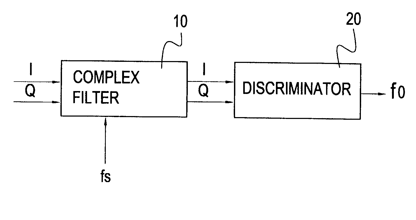
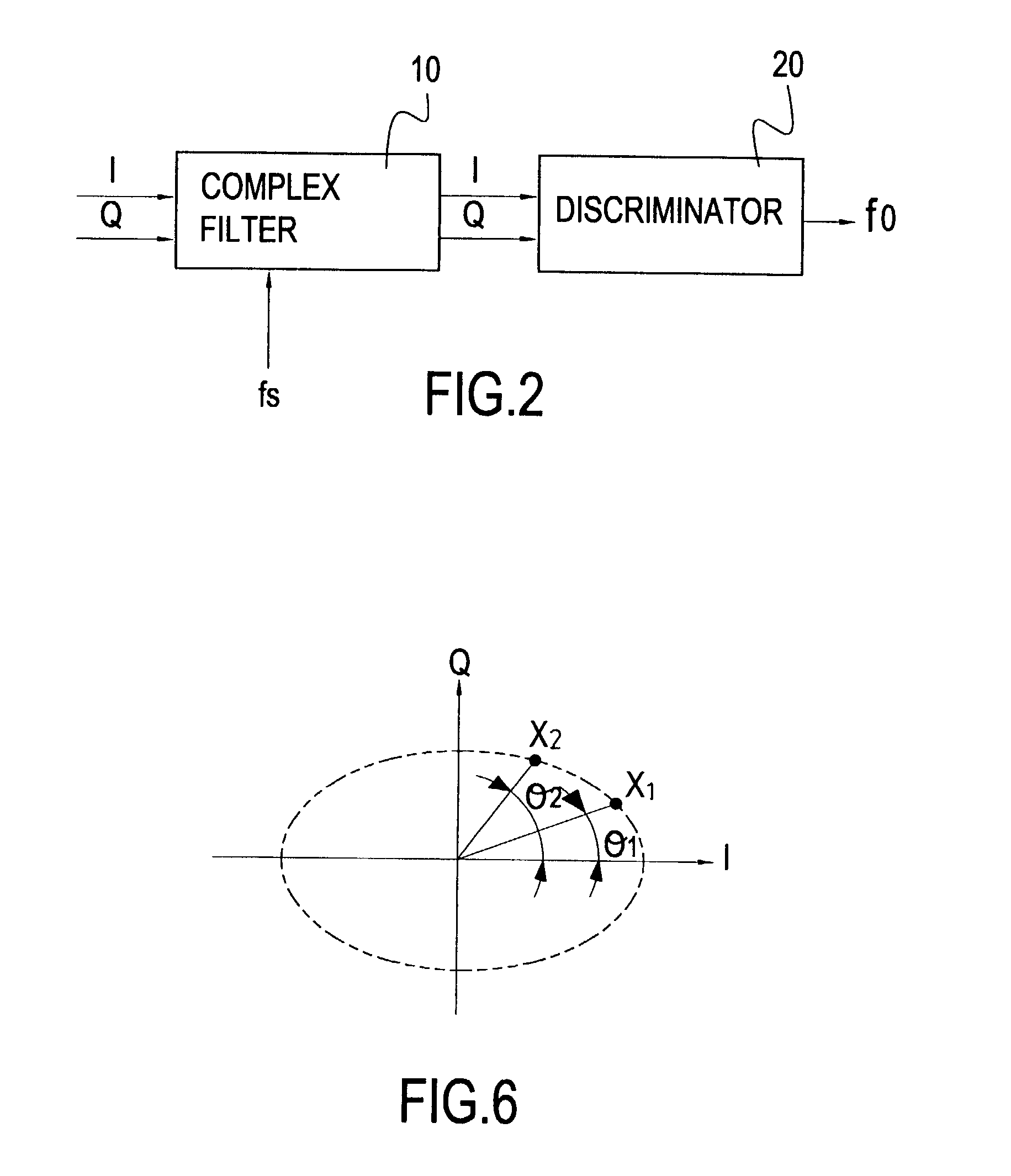
[0009] The second objective of the present invention is to provide an apparatus for detection of single frequency / multi-frequency signals, wherein a complex filter receives two consecutively sampled signals from two sampling points, and a frequency discriminator then uses a complex function to extrapolate the phase difference from the two sampled signals. When applied to a given inverse trigonometric function, the actual demodulated frequency can be derived from the phase difference. Since the frequency computation is largely performed with digital processing without using any high frequency counters, the power requirements for the circuit can be significantly reduced.
[0010] The third objective of the present invention is to provide a frequency analyzer that employs a complex function to compute the demodulated frequency, which greatly reduces the complexity of the circuit design and the related manufacturing costs associated with the introduction of new semiconductor technology.

Problems solved by technology

Yet to meet the extremely high frequency requirement for signal sampling, the circuit design becomes much more complicated, and the operating specifications of circuit components also have to match the high standards.
However, the result is more power for the control circuit and relatively high component costs due to the use of a critical component, the bandpass filter.
Replacements with other semiconductor circuits are not available.

Method used


Image

  • Frequency analyzer
  • Frequency analyzer
  • Frequency analyzer

Examples


Embodiment Construction

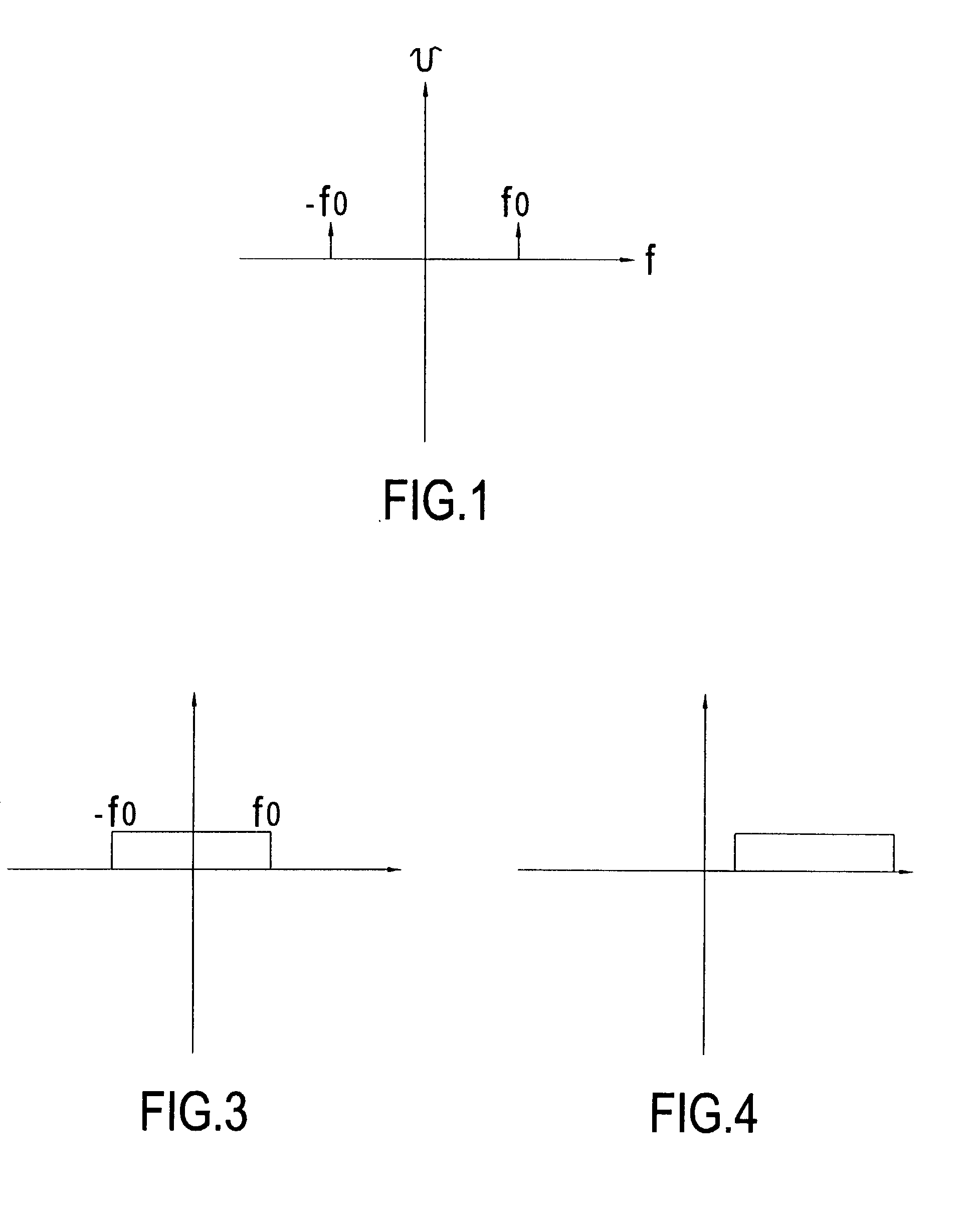
[0025] According to the principle of Fourier transforms, a continuous periodic wave can be expressed in the form of the summation of a series of sinusoidal components. Alternatively, the series can be charted by frequency spectrum. The Fourier series of a periodic waveform can be expressed in the frequency domain by symmetric frequency line spectrum. For example 1 cos o t = j o t + - j o t2 ( 1 )

[0026] The frequency spectrum of a sinusoidal wave contains both positive frequency (f.sub.0) and negative frequency (-f.sub.0) components in the frequency domain as shown in FIG. 1. Either one can be used for frequency computation depending on the choice, but in the current embodiment only the positive frequency component is used for illustration, specifically the e.sup.j.omega..sup..sub.o.sup.t part. According to the complex function, the complex form of the expression e.sup.j.omega..sup..sub.o.su-p.t=cos .omega..sub.ot+j sin .omega..sub.ot is composed of the real part that is the first pa...


PUM


Abstract

A frequency analyzer uses a new approach to determine simple and multi-frequency components. The invention mainly comprises a complex filter and a frequency discriminator. The real number part of the input frequency can be represented by a frequency spectrum composed of both positive frequencies and negative frequencies. The complex filter receives an input signal through two sampling points, and then the frequency discriminator computes the phase difference between two sampled signals from these two consecutive sampling points. After applying an inverse trigonometric function, the demodulated frequency is derived from the phase difference. Using a complex function to derive the demodulated frequency is more advantageous in that many high-frequency sampling circuits become unnecessary, thus reducing the power consumption of the frequency demodulation circuit.

Description

[0001] 1. Field of the Invention[0002] The present invention relates to a frequency analyzer using a new approach to determine a simple frequency and multi-frequency signals, in particular, to a new detection technique that uses a complex function to compute the phase difference from two sampled signals, and applies an inverse trigonometric function to the phase difference to derive the demodulated frequency.[0003] 2. Description of Related Art[0004] Tone detection is often used in telecommunications. Caller-ID or the display of the caller's phone number on a recipient's mobile phone is one of its many applications. Conventional signaling techniques often employed in telecommunications are Frequency Shift Keying (FSK), Dual Tone Multi-Frequency (DTMF) and Channel Associated Signaling (CAS).[0005] With reference to FIG. 9, the process of tone detection constitutes first passing an input signal through a bandpass filter to block signals and noise outside a specific frequency range. Th...

Claims


Application Information

Patent Timeline
IPC IPC(8): H04L27/148
CPCH04L27/148
Inventor CHEN, TZONG-KWEI
Owner WINBOND ELECTRONICS CORP
Learn More