
Single-stage centrifugal pumping unit

a centrifugal pumping unit, single-stage technology, applied in the direction of pump installation, non-positive displacement fluid engine, liquid fuel engine components, etc., can solve the problems of significant reduction in efficiency and reliability, increase in reliability of operation, loss of energy, etc., to achieve peak efficiency and simplify design

Inactive Publication Date: 2019-08-08
OBSHCHESTVO S OGRANICHENNOJ OTVETABTVENNOSTJU NEFTEKAMSKIJ MASHINOSTROITELNYJ ZAVOD OOO NKMZ
View PDF1 Cites 1 Cited by
  • Summary
  • Abstract
  • Description
  • Claims
  • Application Information

AI Technical Summary

Benefits of technology

The present invention is about a single-stage centrifugal pumping unit that has been designed to be efficient in non-normal modes with a simplified design that is applicable to different situations. It includes a centrifugal double entry pump, an electric motor, a coupling, a support frame, and other components. The invention features a separate volute that can be easily replaced, and its parameters are calculated to ensure optimal performance. The volute has a baffle to separate fluid flow during movement. The technical effects of the invention are improved efficiency and flexibility in pumping.

Problems solved by technology

However, when operating such a pump at feed rates below nominal, pressure pulsations, pump vibration are increased, which leads to substantial reduction in its efficiency and reliability.
These disadvantages of the known pumps are due to their design involving use of only one volute, designed only for nominal mode, which results in loss of energy when it interacts with an impeller, which is forced to work in a different mode, i.e., at feed rates above or below nominal.
However despite the fact that replacement of impellers causes some change in the pattern of fluid flow and insignificant increase in pump efficiency in respective non-nominal modes, and some increase in the reliability of its operation as compared to the operation of the impeller pump in nominal mode, this measure is insufficient because the design of the pump also provides for using only one volute designed only for nominal mode, which results in loss of energy when it interacts with the impeller designed for non-nominal mode.
Energy loss in this case leads to additional loss of efficiency of up to 8% with respect to optimal combination of impeller and volute.
This results in the same disadvantages as described above due to use of the same volute, because fluid energy conversion occurs along the entire length of the volute, which in its turn is calculated for maximum flow rather than for an optimum one.
Even in case of optimal interaction of the impeller and the guide apparatus in such a pump energy losses are inevitable, since after the fluid passes through the impeller and the guide apparatus, it enters the outlet, calculated for only one mode.
Moreover, if replacement of already operating pump installed on the line with a pump having other design characteristics is necessary, dismantling of the pipeline will be also necessary, which is a laborious operation requiring investing additional funds to the price of a new pump, while the need to use guide apparatuses will complicate a pump design, increase cost of its manufacture, and increase adverse noise impact on the environment.

Method used


Image

  • Single-stage centrifugal pumping unit
  • Single-stage centrifugal pumping unit
  • Single-stage centrifugal pumping unit

Examples


Embodiment Construction

[0012]To ensure comprehensive understanding of the essence of the present invention, its numerous specific characteristics will be described hereinafter.

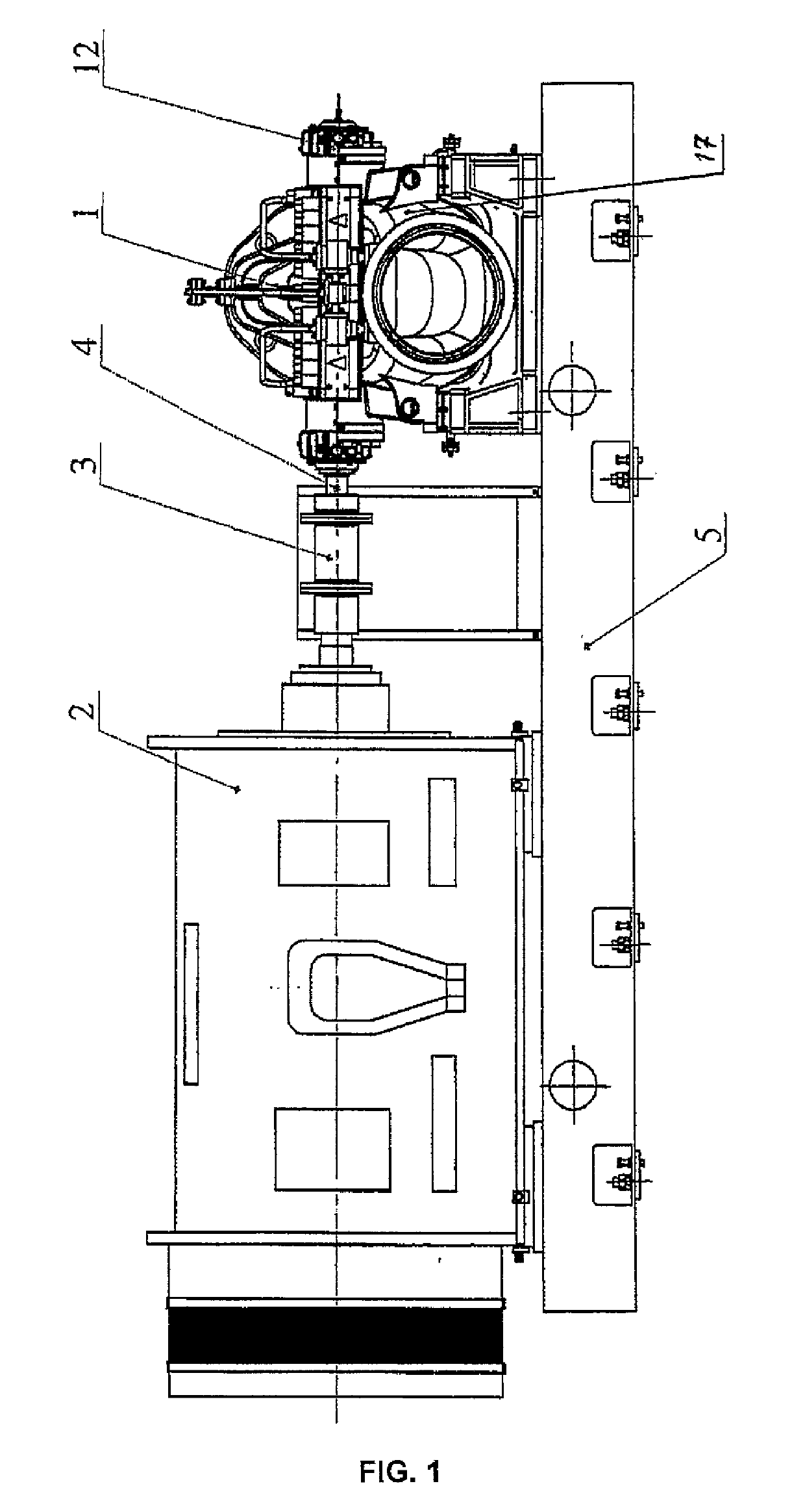
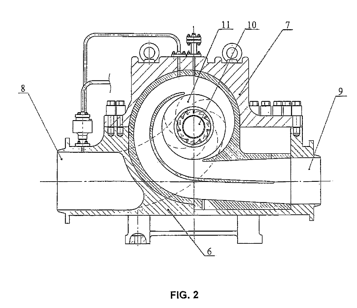
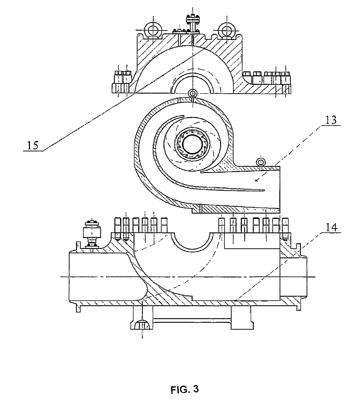
[0013]According to the present invention, a single-stage centrifugal pumping unit comprises an electric drive motor 2, a centrifugal single-stage double entry pump 1 (hereinafter, the pump), a coupling 3, connecting their shafts, a pump housing 17, which consists of a base 6 and a cover 7, an inlet manifold 8 and an outlet manifold 9, a rotor 10 with an impeller 11, the rotor being installed in support bearings 12, a volute 13, and a support frame 5 for mounting the pump housing 17 and the electric motor 2 thereon. As shown in FIG. 3, the volute 13 is configured in the form of a separate, independent component, and parts of the outside surface thereof, which are intended to be accommodated in cradles 14 and 15 provided for this purpose in the housing 6 and the cover 7, correspond to the shape of the surfaces of said cradles 14 and 1...


PUM


Abstract

The invention relates to mechanical engineering, namely to pumping installations designed for pumping water, water solutions, as well as oil, oil products and the like through the main, process and auxiliary pipelines, and is directed toward providing a single-stage centrifugal pumping unit which demonstrates peak efficiency in non-nominal modes while having a simplified design and being universal in nature. To this end, a single-stage centrifugal pumping unit comprises a centrifugal single-stage double entry pump, an electric drive motor, a coupling, connecting their shafts, a support frame for mounting the pump housing and the electric motor thereon, a housing, which consists of a base and a cover, inlet and outlet manifolds, a rotor with an impeller mounted thereon, the rotor being installed in support bearings, and a volute configured according to the invention in the form of a separate, independent component, and parts of the outside surface thereof, which are intended to be accommodated in cradles provided for this purpose in the cover and the housing, correspond to the shape of the surfaces of said cradles. The impeller and the volute are replaceable as a pair, the parameters of the impeller and the volute in each pair are calculated to provide maximum efficiency while ensuring the requisite feed and pressure. The replaceable volutes are made as an integrated cast component and comprise a baffle separating the fluid flow during the movement.

Description

TECHNICAL FIELD[0001]The invention relates to mechanical engineering, namely to pumping installations designed for pumping water, water solutions, as well as oil, oil products and the like through the main, process and auxiliary pipelines.BACKGROUND ART[0002]From the catalog “Centrifugal oil pumps for main pipelines”, edited by V. A. Golovin, M., CINTIhimneftemash, 1989, p. 5, have been known centrifugal horizontal single-stage HM type pumps designed for pumping oil through main pipelines comprising a housing with a volute, and a double entry impeller disposed in the housing. Using the volute therein is directed to reducing radial forces acting on a rotor, and thus reducing vibration and improving pump reliability. However, when operating such a pump at feed rates below nominal, pressure pulsations, pump vibration are increased, which leads to substantial reduction in its efficiency and reliability. These disadvantages of the known pumps are due to their design involving use of only...

Claims


Application Information

Patent Timeline
Patent Type & Authority Applications(United States)
IPC IPC(8): F04D29/42F04D29/62F04D29/22
CPCF04D29/42F04D29/62F04D29/2222F04D29/2238F04D29/22F04D1/006F04D13/06F04D29/426F04D29/628F05D2230/61
Inventor KUSHNAREV, VLADIMIR IVANOVICHKUSHNAREV, IVAN VLADIMIROVICHOBOZNY, YURY SERGEEVICH
Owner OBSHCHESTVO S OGRANICHENNOJ OTVETABTVENNOSTJU NEFTEKAMSKIJ MASHINOSTROITELNYJ ZAVOD OOO NKMZ
Learn More