
Matching networks, inductors, and coupled-inductor capacitive wireless power transfer circuit and related techniques

a technology of matching network, which is applied in the field of matching network, inductors, coupledinductor capacitive wireless power transfer circuit, can solve the problems of limiting the operating frequency of such systems, the major loss source of inductors used in matching networks, and the potential size reduction of such systems, so as to improve the efficiency of a capacitive wpt system, reduce the size, and enhance the effect of efficiency

Active Publication Date: 2022-08-16
UNIV OF COLORADO THE REGENTS OF
View PDF4 Cites 0 Cited by
  • Summary
  • Abstract
  • Description
  • Claims
  • Application Information

AI Technical Summary

Benefits of technology

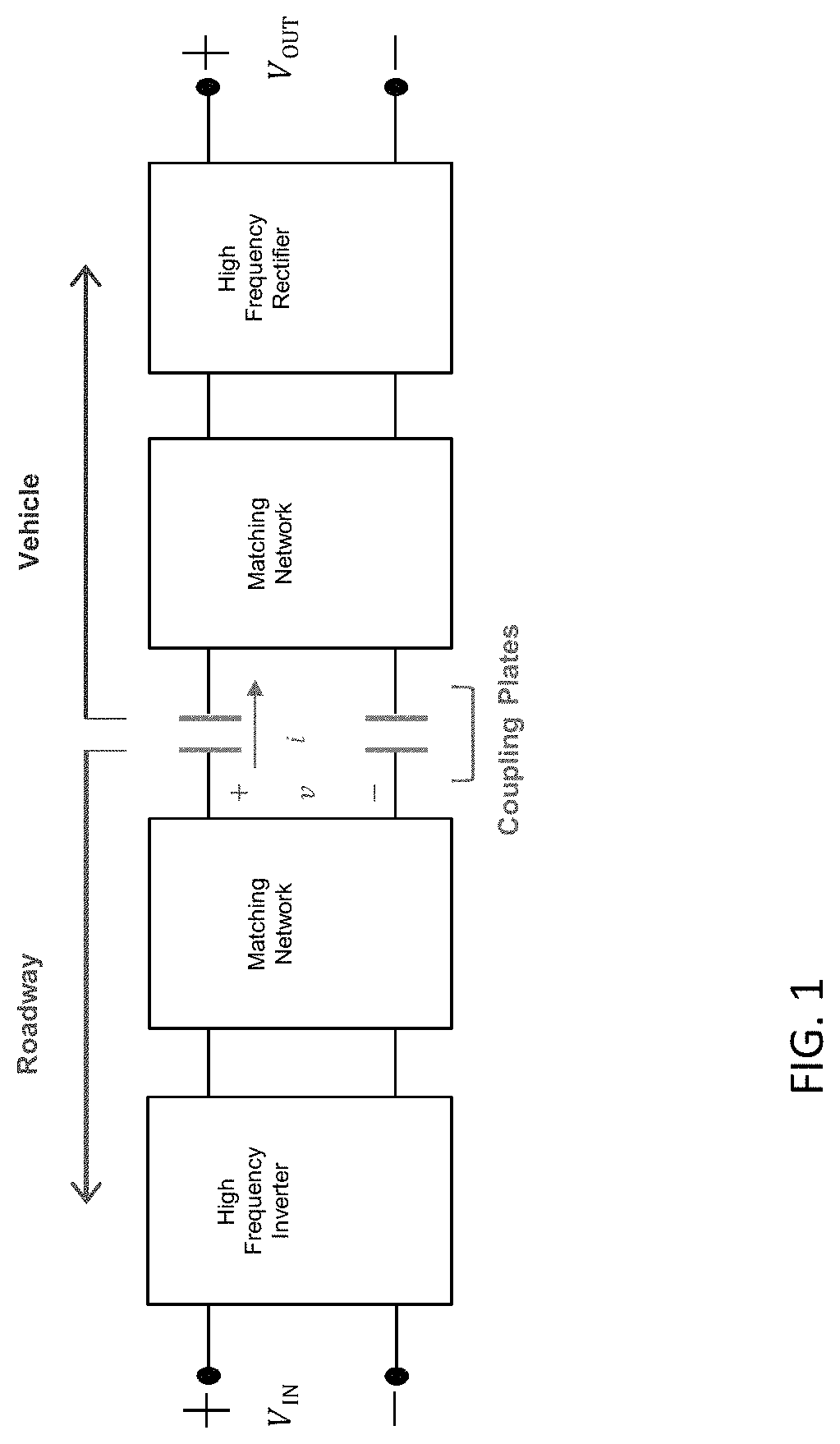
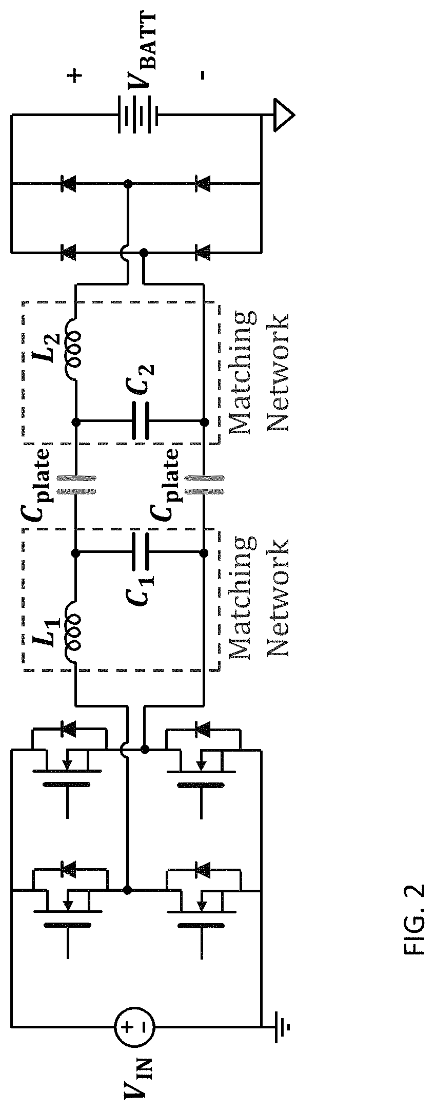
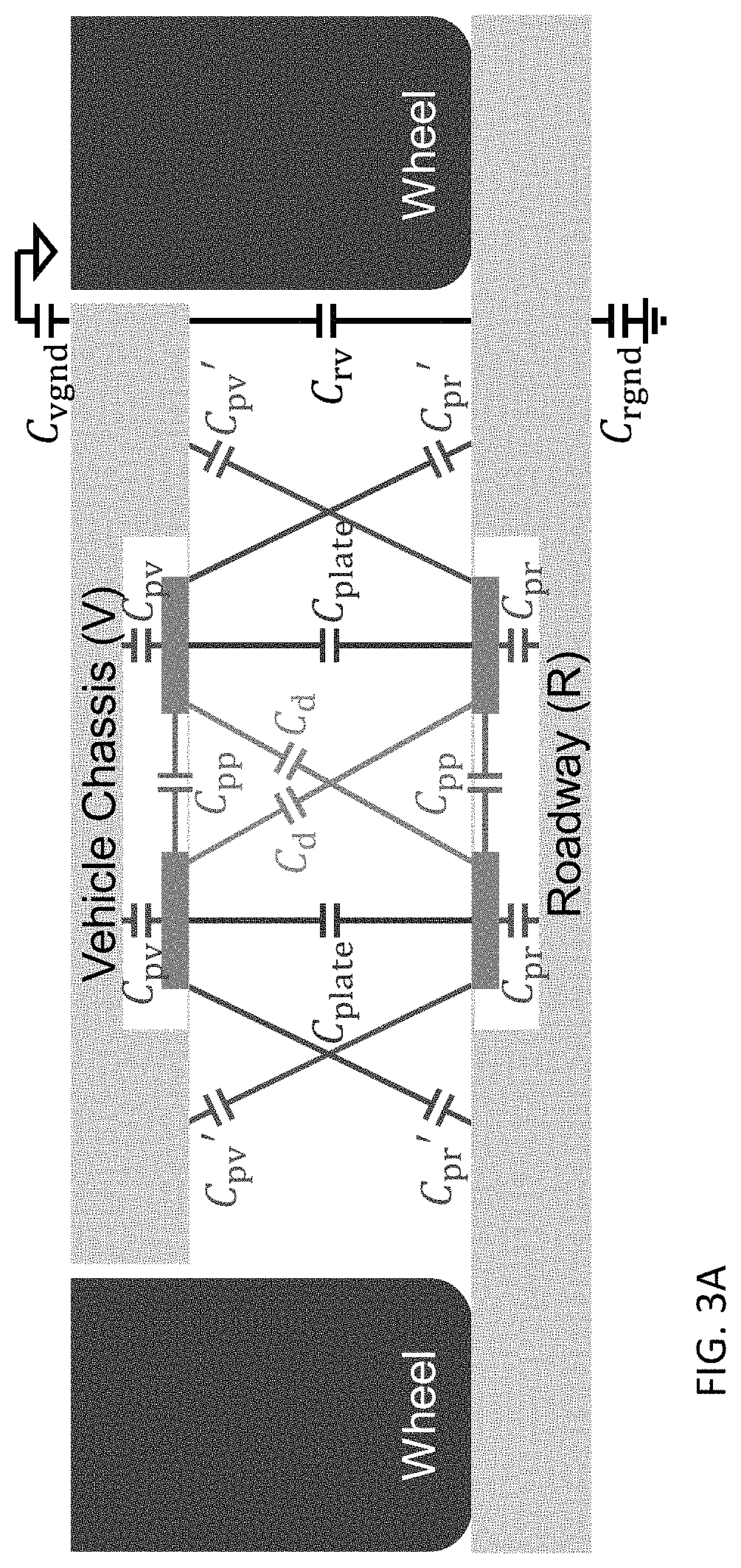
[0013]In some implementations, in order to eliminate parasitic ground currents for example, the inductors in matching networks of high-frequency capacitive WPT systems can be split, with one half (or portion) placed in a forward path, and the other half (or portion) in a return path. This disclosure introduces a new approach to designing matching networks where the split inductors are coupled into a single magnetic structure. The coupled-inductor based matching network, in conjunction with a high operating frequency, significantly enhances the efficiency of a capacitive WPT system, and reduces its size. Efficiency can be further enhanced by realizing the matching network capacitors entirely using parasitic capacitances, thus eliminating the losses associated with on-board capacitors.
[0014]In one example implementation, a 13.56-MHz 12-cm air-gap prototype capacitive WPT system is designed, built and tested. This system transfers 884 W at an efficiency of 91.3%, achieving a power transfer density of 29.5 kW / m2. Additionally, the prototype system achieves a peak efficiency of 95% when transferring 348 W. Compared to a prototype 6.78-MHz split-inductor capacitive WPT system, the 13.56-MHz coupled-inductor system exhibits up to 53% reduced losses and 69% reduced inductor volume.

Problems solved by technology

Ferrites are fragile, bulky, expensive, and introduce core losses that limit the operating frequency of such systems, and consequently, their potential for size reduction.
The inductors used in the matching networks are the major source of losses in WPT systems.

Method used


Image

  • Matching networks, inductors, and coupled-inductor capacitive wireless power transfer circuit and related techniques
  • Matching networks, inductors, and coupled-inductor capacitive wireless power transfer circuit and related techniques
  • Matching networks, inductors, and coupled-inductor capacitive wireless power transfer circuit and related techniques

Examples


example variants

[0042]The coupled inductor presented above is merely an example of its numerous possible implementations. Some example implementations are provided below, with terminal markings A, B, C, and D aligning to how the coupled inductor is connected to the circuit of FIG. 5(a).

[0043]FIG. 10 shows an example implementation of a coupled inductor constructed with a flat wire.

[0044]FIG. 11 shows an example implementation of a coupled inductor utilizing two parallel windings. In further implementations, two or more parallel windings may also be used.

[0045]FIG. 12 shows another example implementation of a coupled inductor wound on a semi-toroid with interleaved-foil wire. The interleaved-foil wires, in this particular example, are connected in parallel and are shown in black and white.

[0046]FIG. 13 shows yet another example implementation of a coupled inductor wound on a toroid with interleaved-foil wire.

[0047]FIG. 14 shows an example implementation of a capacitive WPT system comprising multi-st...


PUM

PropertyMeasurementUnit
parasitic capacitancesaaaaaaaaaa
electric fieldsaaaaaaaaaa
voltageaaaaaaaaaa

Abstract

In one implementation, a matching network is provided comprising a pair of input terminals; a pair of output terminals; and at least two reactive components disposed between the pair of input terminals and the pair of output terminals. At least one of the reactive components comprises a coupled-inductor. In various implementations, the second reactive component can be a capacitor, and the capacitor can be at least partially realized using the parasitic capacitances of the environment. The matching network may be disposed in a capacitive wireless power transfer (WPT) system. In other implementations, inductors and coupled-inductors are further provided. In some implementations, for example, an inductor, such as but not limited to a coupled-inductor, may comprise a toroidal or semi-toroidal core comprising foil wire interleaved without notches.

Description

CROSS-REFERENCE TO RELATED APPLICATIONS[0001]This application claims the benefit of U.S. provisional application No. 62 / 644,246, entitled “Air-Gap Capacitive Wireless Power Transfer System for Electric Vehicle Charging” and filed Mar. 16, 2018, which is hereby incorporated by reference as though fully set forth herein.BACKGROUNDa. Field[0002]The instant disclosure relates to coupled inductor capacitive wireless power transfer circuits, components thereof, and techniques for controlling coupled inductor capacitive wireless power transfer circuits.b. Background[0003]Wireless power transfer (WPT) has utility in a vast array of applications, including electric vehicles (EVs), material handling equipment, robotics, unmanned aerial vehicles (UAVs), portable electronics, and biomedical implants. For example, wireless charging can eliminate the inconvenience associated with plugging in and the wear and tear of wires and connectors. By eliminating manual plug-in, WPT also makes self-driving ...

Claims


Application Information

Patent Timeline
Patent Type & Authority Patents(United States)
IPC IPC(8): H03H7/38H02J50/05B60L53/30B60L53/12H01F27/28H02J7/02
CPCH03H7/38B60L53/12B60L53/32H01F27/2823H02J50/05H02J7/025H03H7/09H01F27/2895H01F27/2847B60L5/005B60L5/42Y02T90/14Y02T10/7072Y02T10/70
Inventor AFRIDI, KHURRAMREGENSBURGER, BRANDONSINHA, SREYAMKUMAR, ASHISH
Owner UNIV OF COLORADO THE REGENTS OF
Learn More