Liquid-phase growth apparatus and method

Inactive Publication Date: 2003-10-02
CANON KK
View PDF5 Cites 3 Cited by
  • Summary
  • Abstract
  • Description
  • Claims
  • Application Information

AI Technical Summary

Problems solved by technology

Unfortunately, in a dipping process that includes dipping a substrate held with a

Method used


Image

  • Liquid-phase growth apparatus and method
  • Liquid-phase growth apparatus and method
  • Liquid-phase growth apparatus and method

Examples


Embodiment Construction

[0054] A nonlimiting example of the present invention will now be described. The liquid-phase growth apparatus according to the present invention was used for forming a monocrystalline silicon thin film. Substrates were disposed radially as shown in FIG. 8.

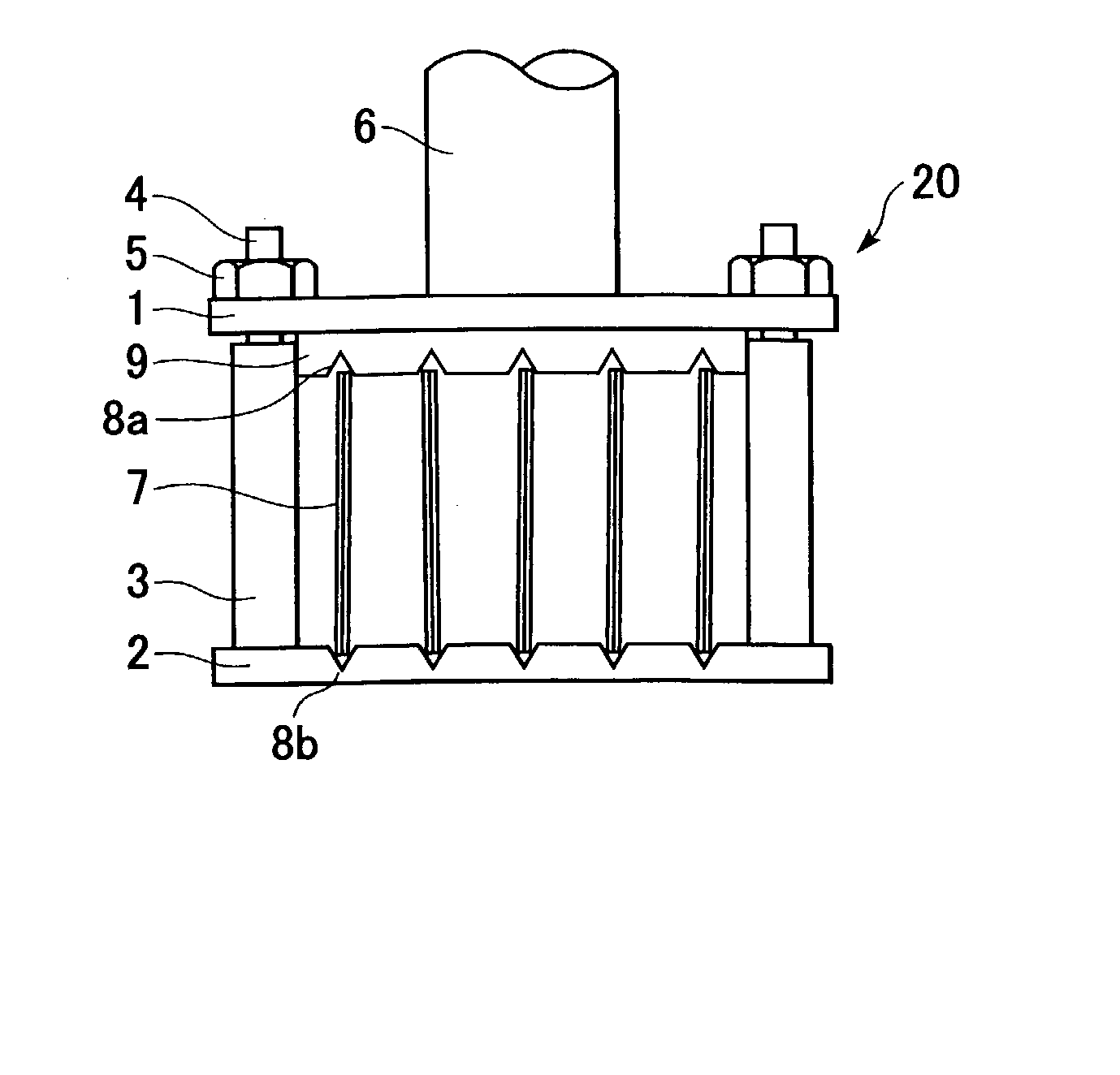
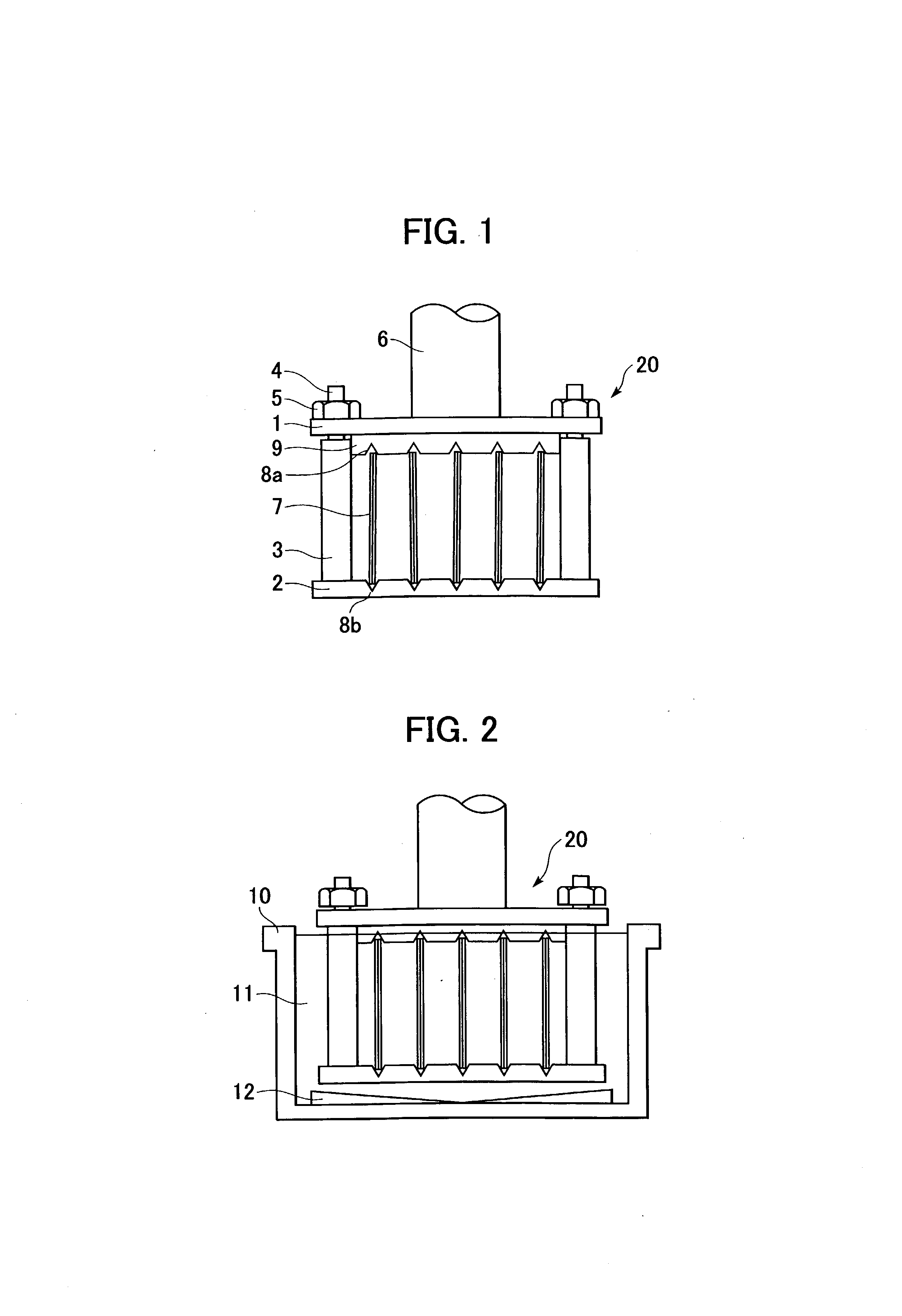
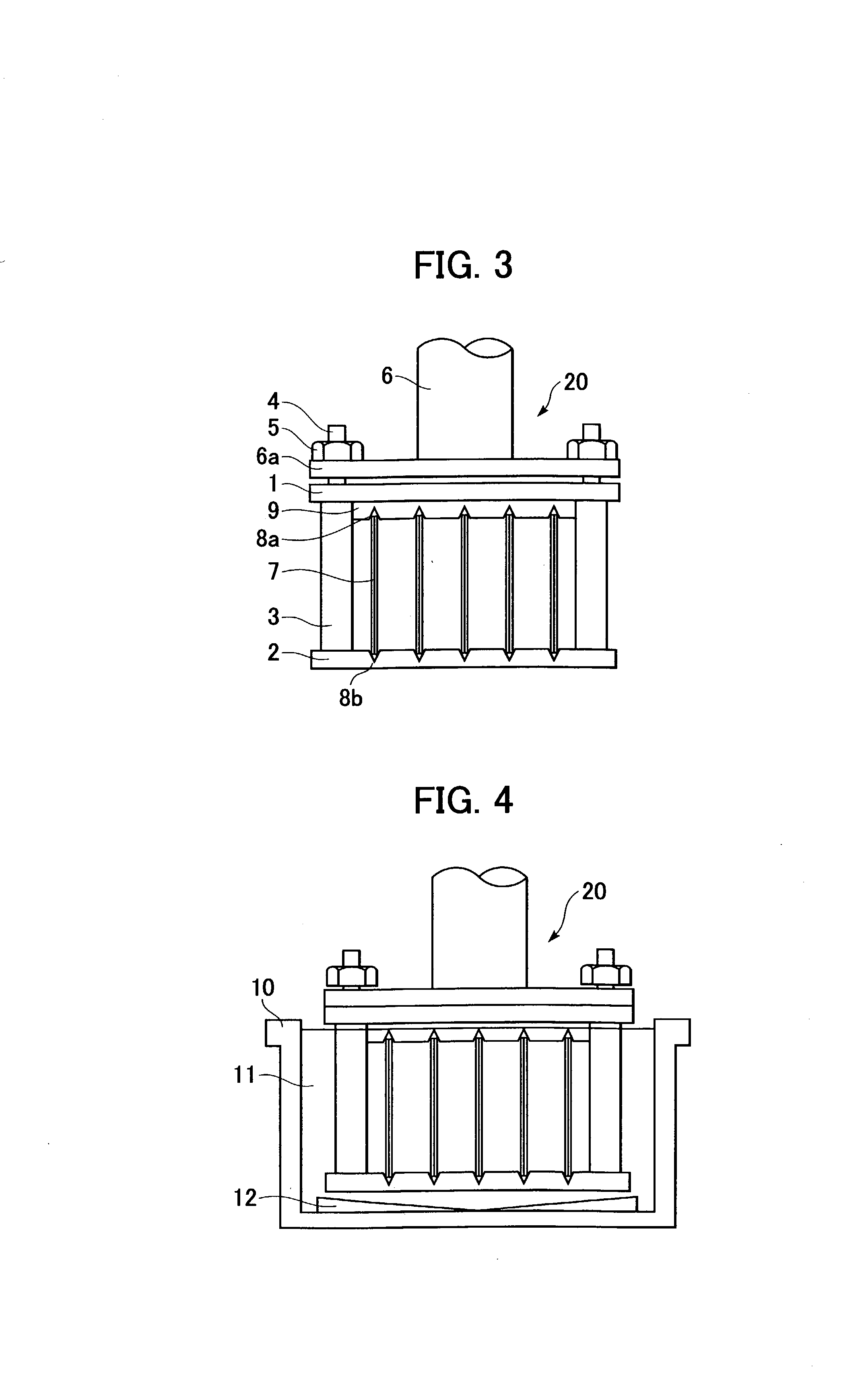
[0055] Substrates 7 were p+ silicon substrates having a square shape with a side of 125 mm and a thickness of 0.6 mm. Each silicon substrate was anodized to form a porous surface layer with a thickness of 12 .mu.m. Rear faces of two substrates were put into close contact with both surfaces of a quartz square dummy plate with a side of 125 mm and a thickness of 0.6 mm, and this substrate combination was placed into the substrate holder unit 20. The receiving component 2 was composed of quartz and had a diameter of 350 mm and a thickness of 5 mm. The receiving component 2 had V grooves 8b that supported 5 mm from each end of the substrate combination. Each V groove 8b had a width of 2.5 mm and a cross-sectional angle of 60.degree.. ...


PUM


Abstract

A liquid-phase growth apparatus for growing a crystal on a substrate includes a crucible containing a solution that contains a raw material for forming the crystal, and a substrate holder for vertically holding the substrate. The substrate holder includes connectors, a receiving component, and a push component. The receiving component and the push component are opposite to each other and are connected by the connectors. The push component holds an upper portion of the substrate while the receiving component holds a lower portion of the substrate. The substrate holder containing the vertically held substrate is dipped into the solution. The receiving component ascends with buoyancy in the solution contained in the crucible, so that the substrate is now held securely and prevented from cracking due to thermal expansion.

Description

[0001] 1. Field of the Invention[0002] The present invention relates to a liquid-phase growth apparatus for growing a crystal on a seed substrate that is vertically held with a substrate holder and is dipped in a solution containing a solute (raw material) for forming the crystal in a crucible, and to a liquid-phase crystal growth method using the apparatus.[0003] 2. Description of the Related Art[0004] Liquid-phase growing is known as a method for preparing a high-quality monocrystalline thin film at relatively low temperature. Unfortunately, in a dipping process that includes dipping a substrate held with a substrate holder in a solution, films are deposited on two faces of the substrate.[0005] Some methods are proposed for depositing a thin film only on one face of the substrate. For example, a substrate is placed on a platinum holder and fixed with fixing claws to inhibit growth of the film on the rear face of the substrate. In another proposed method, two substrates that are in...

Claims


Application Information

Patent Timeline
IPC IPC(8): C30B19/02C30B19/06C30B29/06H01L21/208
CPCC30B19/02C30B19/068Y10T117/10Y10T117/1024C30B29/06
Inventor MIZUTANI, MASAKINAKAGAWA, KATSUMIYOSHINO, TAKEHITONISHIDA, SHOJI
Owner CANON KK
Why Eureka
Try Eureka