
Air heating device for integration into an air-conducting housing arrangement

a technology of air heating device and air-conducting housing, which is applied in the direction of vehicle heating/cooling device, railway heating/cooling, vehicle components, etc., can solve the problem of difficult to ensure that different systems are constructed in such a way

Inactive Publication Date: 2003-09-18
J EBERSPAECHER GMBH & CO KG
View PDF5 Cites 14 Cited by
  • Summary
  • Abstract
  • Description
  • Claims
  • Application Information

AI Technical Summary

Benefits of technology

[0005] The present invention has as its object to supply an air-heating device, which can be adapted in a simple manner for integration into an air-conducting housing arrangement, for example, a housing arrangement of a vehicle air conditioner.
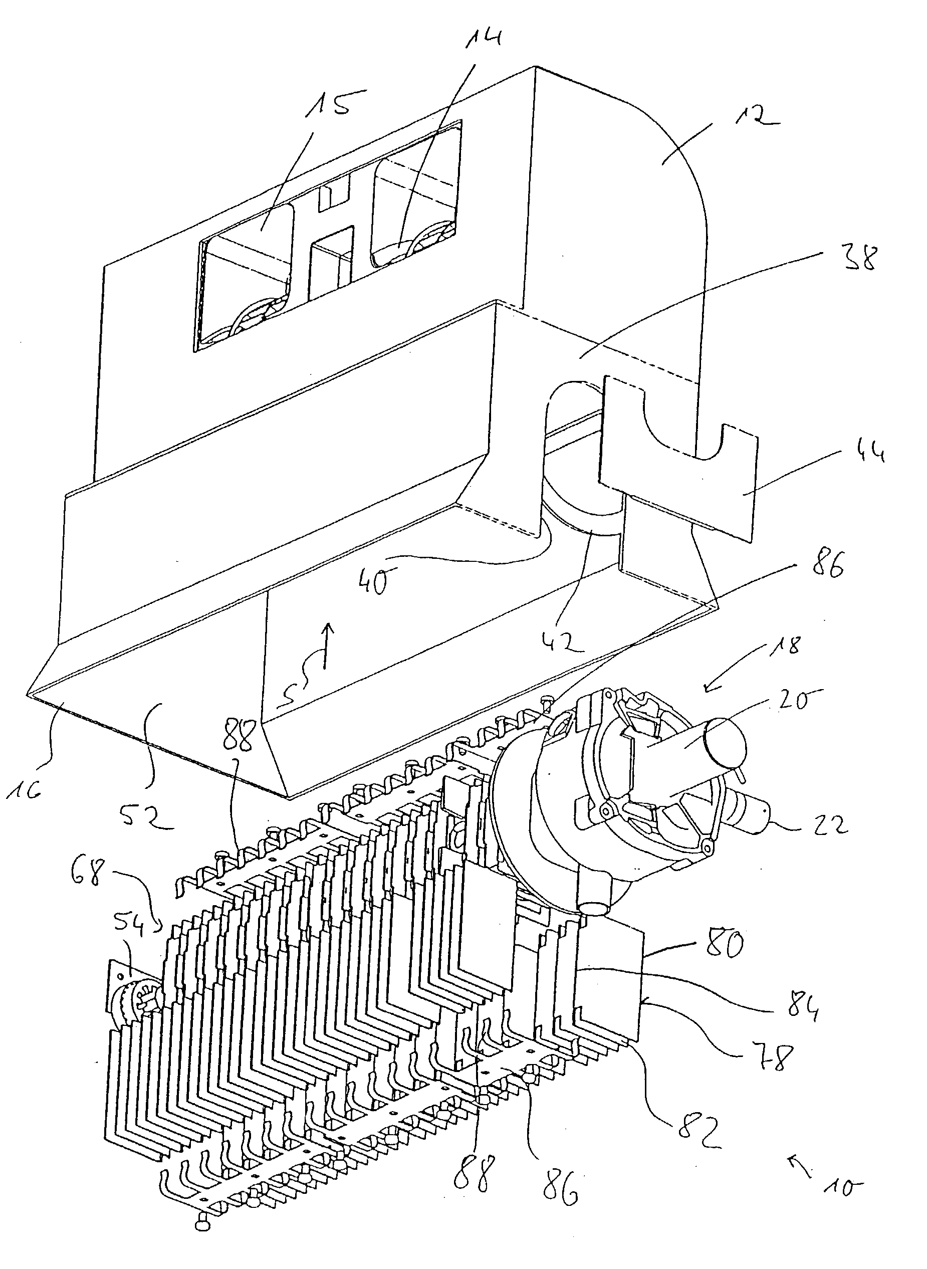
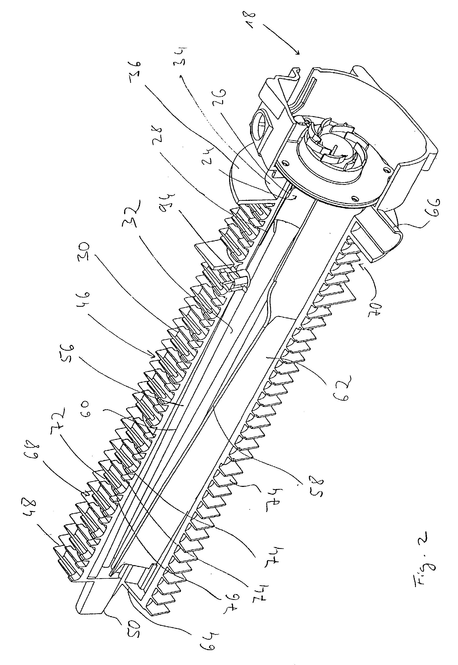
[0007] Components of an air-heating device, which take up considerable space, are the ribs serving for heat transfer to the air to be heated. The greater the heat transfer surface of these ribs around which flow can occur, the more efficiently can the heat be utilized which is generated in the air heating device. The present invention now provides for a high degree of variability in the region of these heat transfer ribs, since these are at least partially constituted separately and thus can be selected or shaped to match a respective housing arrangement into which the air heating device is to be integrated. The other important and notably expensive components of the air heating device, such as, e.g., the heat exchanger region and the burner region, can be retained unchanged here as a basic type for numerous different housing arrangements provided for integration, considerably reducing the integration costs.
[0008] For example, the air heating device according to the invention can be constructed such that the heat exchanger body is elongate in the direction of a body longitudinal axis, and that at least a portion of the heat transfer ribs for the air to be heated provide a heat transfer surface arranged substantially orthogonally of the body longitudinal axis. In order to make the coupling of the heat transfer ribs to the heat exchanger body possible in a simple manner, with the attainment of a good heat transfer contact between these assemblies, it is proposed that the heat transfer rib arrangement includes at least one heat transfer rib module, and that the at least one heat transfer rib module includes a coupling region constituted for thermal coupling to the heat exchanger body and also at least one heat transfer rib adjoining the coupling region. The heat transfer contact can thereby be further improved in that the heat exchanger body has on its outside for each coupling region of a heat transfer rib module an abutment structure adapted to the shape of the coupling region. For example, it is possible that the coupling region of the at least one heat transfer rib module and the associated abutment structure are constituted elongate and at least locally curved.

Problems solved by technology

Since however different system components or system regions are frequently supplied by different suppliers, and these different components or system regions are in general also differently constituted for different vehicle types, it is difficult to ensure that such combination is possible for different systems to be constructed.

Method used


Image

  • Air heating device for integration into an air-conducting housing arrangement
  • Air heating device for integration into an air-conducting housing arrangement
  • Air heating device for integration into an air-conducting housing arrangement

Examples


Embodiment Construction

[0024] An air heating device 10 according to the invention, which is in general constituted for insertion into a housing arrangement generally denoted by 12, is shown in FIG. 1 in a partially exploded view. The housing arrangement 12 is, for example, a housing arrangement also receiving a fan 14 (only partially visible) and if necessary an air conditioning unit of a vehicle, and has at its lower region an elongate approximately rectangular receiving aperture 16 into which the air heating device 10 can be introduced when fitting together the air heating device 10 and the housing arrangement 12. The treated air leaves the housing in the region of an air outlet 15.

[0025] The air-heating device 10 includes a burner region generally denoted by 18, the internal structure of which is described in more detail hereinafter with reference to the embodiment shown in FIGS. 4 and 5. Basically it is however mentioned that the burner region 18 is of conventional construction and has a combustion ai...


PUM


Abstract

An air heating device for integration into an air-conducting housing arrangement, particularly a housing arrangement of a vehicle air conditioner, includes a burner region, a heat exchanger region with a heat exchanger body, wherein in the heat exchanger body a combustion exhaust gas conducting space is constituted in which flow the hot combustion exhaust gases produced in the combustion in the burner region. At an outer side of the heat exchanger body a heat transfer rib arrangement with numerous heat exchange ribs for the air conducted in the housing arrangement to flow around; wherein at least a portion of the heat transfer ribs are constituted separately from the heat exchanger body and are kept in heat transfer contact with this.

Description

CROSS-REFERENCES TO RELATED APPLICATIONS[0001] Not applicable.STATEMENT REGARDING FEDERALLY SPONSORED RESEARCH OR DEVELOPMENT[0002] Not applicable.BACKGROUND OF THE INVENTION[0003] The present invention relates to an air-heating device for integration into an air-conducting housing arrangement, particularly a housing arrangement of a vehicle air conditioner.[0004] When integrating additional system components into a vehicle, there exists the endeavor, both because of limited construction space and also on cost grounds, to provide constructional arrangements which are as small as possible by combining different system regions, in which improved interchangeability is attained by merging functions or by common use of different system components. Since however different system components or system regions are frequently supplied by different suppliers, and these different components or system regions are in general also differently constituted for different vehicle types, it is difficul...

Claims


Application Information

Patent Timeline
Patent Type & Authority Applications(United States)
IPC IPC(8): B60H1/08B60H1/00B60H1/18B60H1/22
CPCB60H1/2212B60H2001/2287B60H2001/2271
Inventor SCHLECHT, PATRICCOLLMER, ANDREAS
Owner J EBERSPAECHER GMBH & CO KG
Learn More