
Method for manufacturing a porous ceramic structure

a technology of porous ceramics and manufacturing methods, applied in the field of porous ceramic manufacturing methods, can solve the problems of large temperature difference between the central portion of the molded article and the external surface, cracks of unknown causes in the obtained ceramic structure, and new problems such as cracks

Inactive Publication Date: 2003-08-14
NGK INSULATORS LTD
View PDF4 Cites 39 Cited by
  • Summary
  • Abstract
  • Description
  • Claims
  • Application Information

AI Technical Summary

Benefits of technology

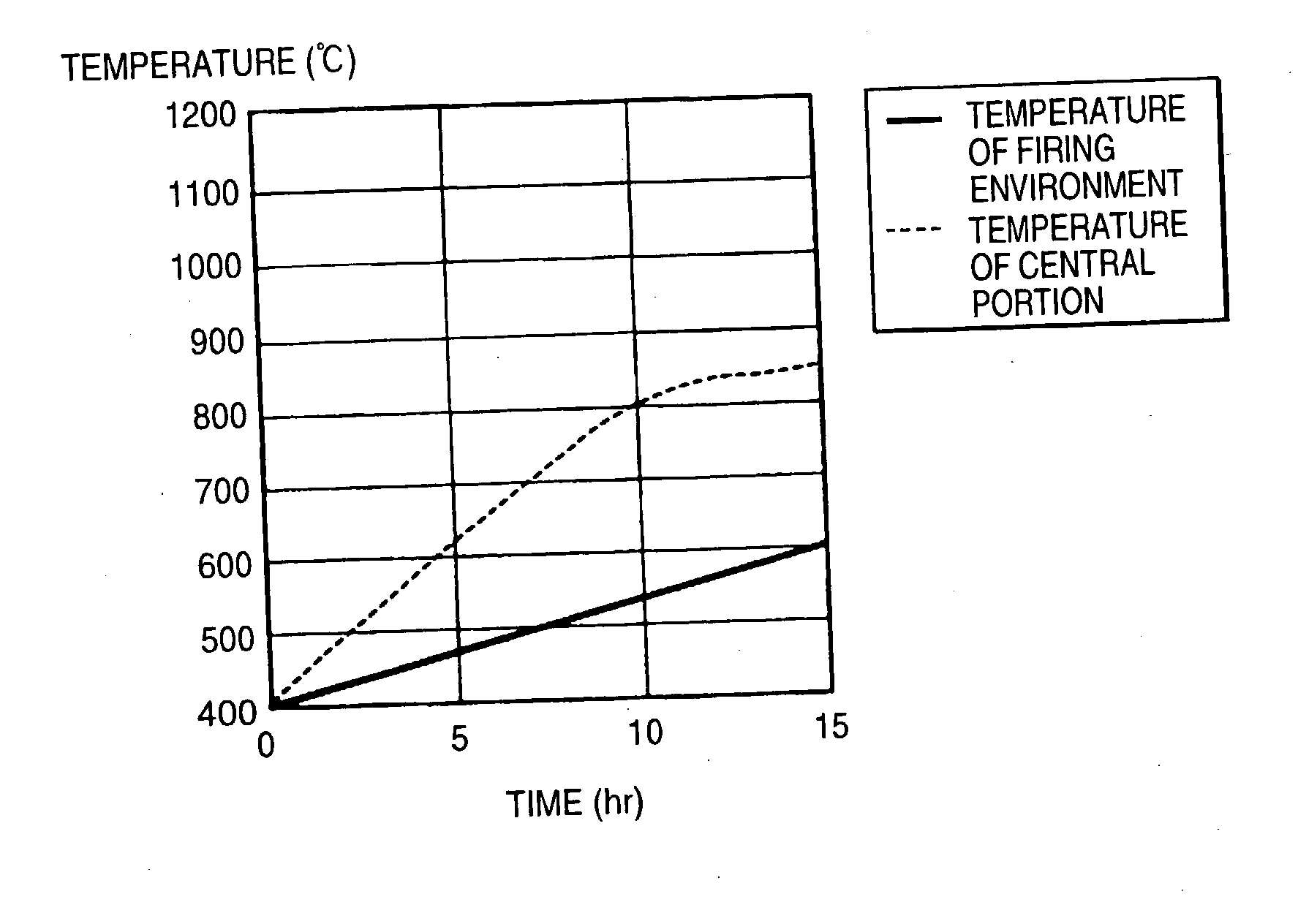
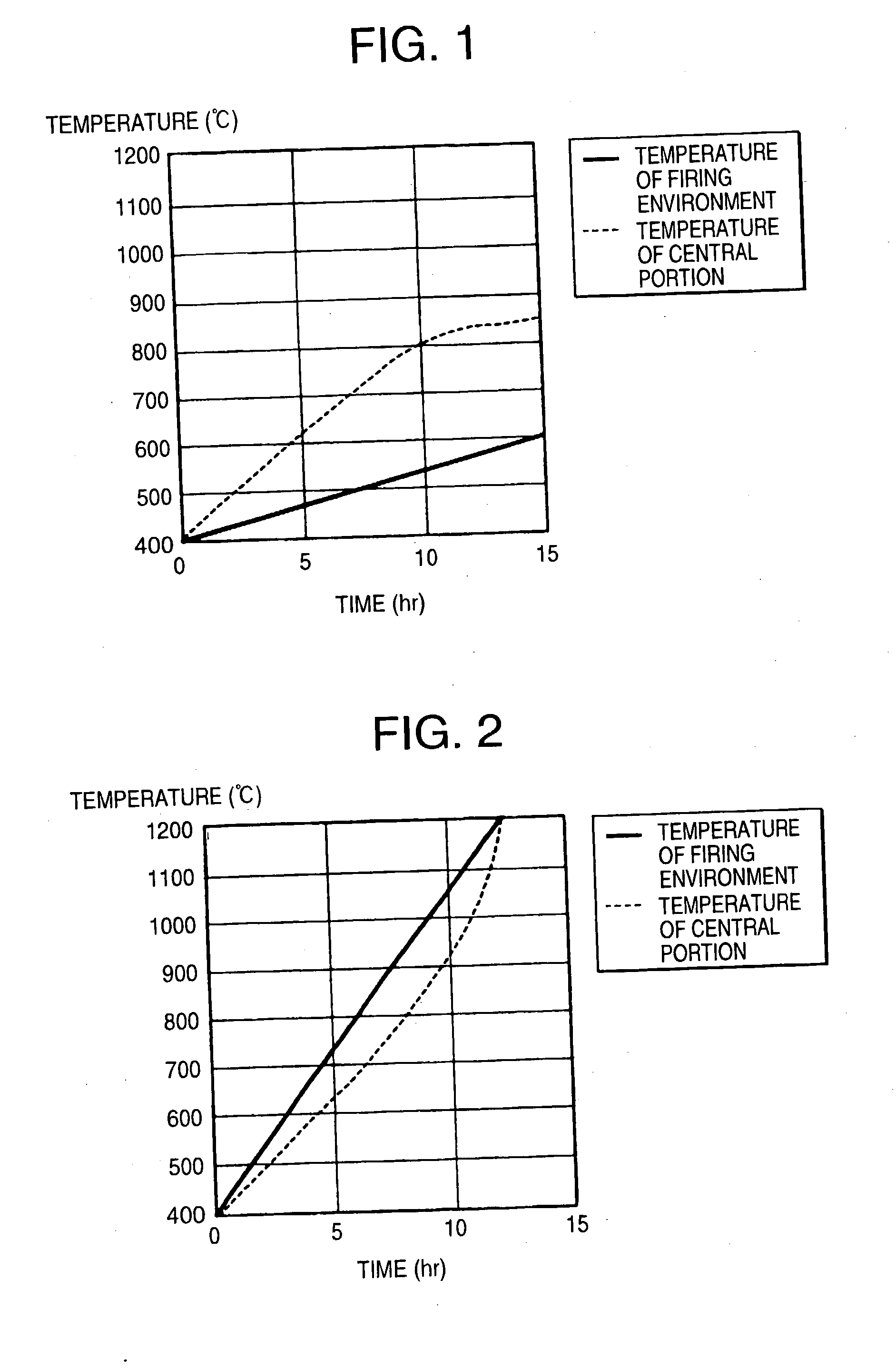
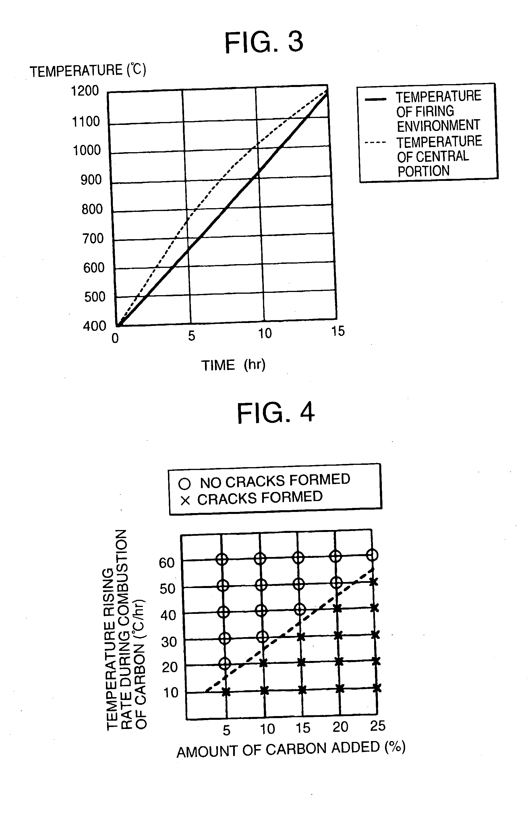
[0008] The present inventors have made intensive studies so as to solve the above problem. As a result, it has been found that there was observed a large difference in temperature between the central portion of a molded article and external surface thereof in a firing step, when a honeycomb structure manufactured has cracks. Thus, they have investigated the causes of the large difference in temperature, and, as a result, found that a large difference in temperature rising rate exists between the central portion of the molded article and a firing environment. Furthermore, it ahs been found that the difference in temperature rising rate becomes significant particularly when carbon and a pore-forming agent which burns at a relatively lower temperature are concurrently used so as to make the honeycomb structure highly porous. This is because pores are already formed at a temperature where carbon starts to burn, so that combustion of carbon is accelerated, and resultantly the temperature of the central portion of the honeycomb structure is apt to increase easily.

Problems solved by technology

However, it has been found that cracks of unknown causes are formed in an obtained ceramic structure, when a molded article containing an increased amount of pore-forming agent such as carbon, or further containing a formable resin and the like in response to such a request of higher porosity is fired in accordance with the same temperature raising program as conventionally used.
The occurrence of the cracks is a new problem in production of a high porosity ceramic structure.
As a result, it has been found that there was observed a large difference in temperature between the central portion of a molded article and external surface thereof in a firing step, when a honeycomb structure manufactured has cracks.
Thus, they have investigated the causes of the large difference in temperature, and, as a result, found that a large difference in temperature rising rate exists between the central portion of the molded article and a firing environment.
That is, it has been found that cracks are formed at a portion of the molded article which has reached this temperature range earlier than other portion thereof due to the difference in the shrinkage due to firing, when such a temperature difference as mentioned above appears between those portions.
Meanwhile, when a molded article comprising a cordierite-forming raw material reaches a temperature range of 800 to 1,200.degree. C., shrinkage due to firing suddenly occurs.
When the tensile stress is significant, cracks are formed in a ceramic structure to be manufactured.
This occurs, for example, when the molded article is large in size or the temperature rising rate of firing environment is extremely high.
However, when a large amount of formable resin which burns out at a low temperature of 300 to 400.degree. C. is added, a number of pores are already formed by that time a pore-forming agent such as carbon which starts to burn at 400.degree. C. or higher is burned, and the pores cause an environment in which the pore-forming agent can burn easily, thereby making it difficult to control a temperature rising rate.

Method used


Image

  • Method for manufacturing a porous ceramic structure
  • Method for manufacturing a porous ceramic structure
  • Method for manufacturing a porous ceramic structure

Examples


example 1

[0071] Firstly, 39.8 wt % of talc (average particle diameter: 21 .mu.m), 18.5 wt % of kaolin (average particle diameter: 11 .mu.m), 14.0 wt % of alumina (average particle diameter: 7 .mu.m), 15.2 wt % of aluminum hydroxide (average particle diameter: 2 .mu.m), and 12.5 wt % of silica (average particle diameter: 25 .mu.m) were mixed together so as to prepare a cordierite-forming raw material.

[0072] Then, a raw material containing 10.0 parts by mass of carbon (average particle diameter: 53 .mu.m), 2.0 parts by mass of foamed resin (average particle diameter: 50 .mu.m), 4 parts by mass of binder, 0.5 parts by mass of surfactant, and 31 parts by mass of water based on 100 parts by mass of the cordierite-forming raw material was charged into a kneader and kneaded for 30 minutes so as to obtain a puddle.

[0073] Then, the obtained puddle was charged into a vacuum kneading machine and kneaded into a cylindrical form which was then put in an extruder to be molded into a honeycomb form. Furthe...

examples 8 and 9

[0082] Honeycomb structures were manufactured in the same manner as in Example 1 except that molded articles were fired in accordance with the temperature raising program 2 shown in Table 1, that a raw material containing 5.0 or 10.0 parts by mass of carbon (average particle diameter: 53 .mu.m) based on 100 parts by mass of the cordierite-forming raw material was used, and that the manufactured honeycomb structures had volumes shown in Table 4 (i.e., 3 L (size: .phi.150 mm.times.L150 mm) and 15 L (size: .phi.250 mm.times.L300 mm)). Production conditions and evaluation results are shown in Table 4 together with those of Example 7. In addition, manners in which temperatures of the central portions of the molded articles and the temperature of a firing environment increased are shown in FIG. 10.

4 TABLE 4 Difference in Temp. between External Rate of Amount of carbon Temp. Surface and Central Occurrence Site Where Volume Added Raising Portion of Molded of Cracks Cracks (L) (Parts by mass...


PUM

PropertyMeasurementUnit
Percent by massaaaaaaaaaa

Abstract

There is here disclosed a method for manufacturing a porous ceramic structure which can produce a high porosity ceramic structure as well as a low porosity ceramic structure without causing cracks at the time of firing. A method for manufacturing a porous ceramic structure comprising the steps of molding a raw material which contains a ceramic material as a main component and a pore-forming agent and then drying and firing the obtained molded article. When the molded article is fired, the temperature of a firing environment is raised substantially in synchronization with the temperature of the central portion of the molded article within a temperature range in which at least a portion of the molded article is shrunk by firing.

Description

BACKGROUND OF THE INVENTION AND RELATED STATEMENT[0001] 1. Field of the Invention[0002] The present invention relates to a method for manufacturing a porous ceramic structure. More specifically, the present invention relates to a method for manufacturing a porous ceramic structure wherein a temperature rising rate of a firing environment is controlled at the time of firing an molded article formed from a puddle containing a ceramic material as a main component so as to suppress occurrence of cracks in the fired molded article. The present method can be applied to the production of a variety of porous ceramic structures. Particularly, it is suitable for production of a porous honeycomb structure having a higher porosity in which the increase of the internal temperature of a molded article is quite striking; said increase being caused by the combustion of a pore-forming agent that is concurrently contained in a molded article at the time of firing the molded article.[0003] 2. Descript...

Claims


Application Information

Patent Timeline
IPC IPC(8): C04B38/00C04B35/195C04B35/634C04B35/636C04B38/06
CPCC04B35/195C04B35/632C04B2235/6584C04B2235/658C04B2235/5436C04B2235/449C04B2235/422C04B35/63424C04B35/63492C04B35/636C04B35/64C04B38/0006C04B38/06C04B38/068C04B2111/343C04B2235/3217C04B2235/3218C04B2235/3418C04B2235/3445C04B2235/349
Inventor MUROI, YUMIWADA, YUKIHISANOGUCHI, YASUSHI
Owner NGK INSULATORS LTD
Learn More