
Clean release tape for EMI shielding

a technology of emi shielding and tape release, which is applied in the direction of film/foil adhesives, layered products, transportation and packaging, etc., can solve the problems of not being able to remove or reposition other electronic devices, the tapes did not cleanly release from the surfaces of the housing parts, and the use of emi shielding tapes that have been used in sealing

Inactive Publication Date: 2003-05-15
PARKER HANNIFIN CORP
View PDF59 Cites 28 Cited by
  • Summary
  • Abstract
  • Description
  • Claims
  • Application Information

AI Technical Summary

Benefits of technology

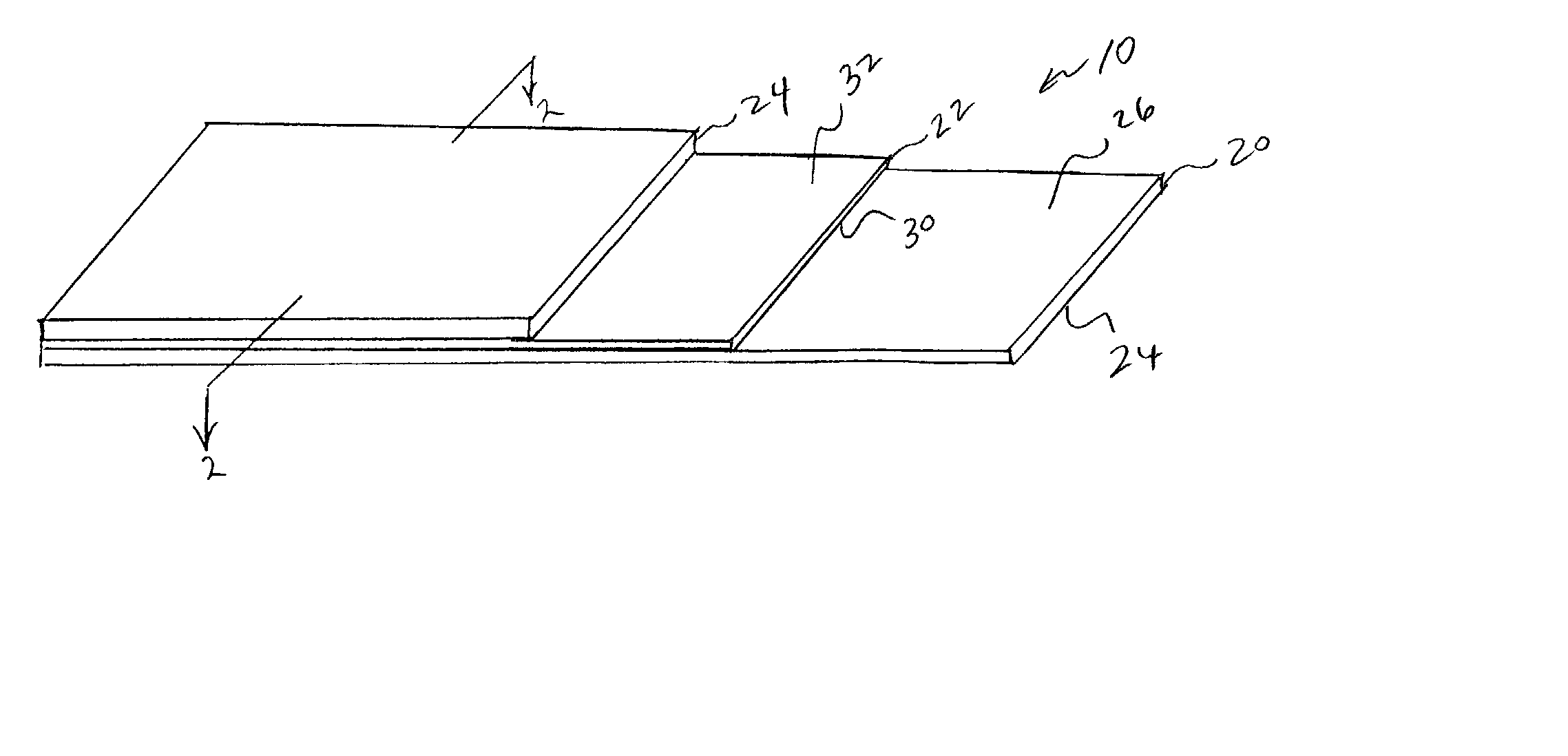
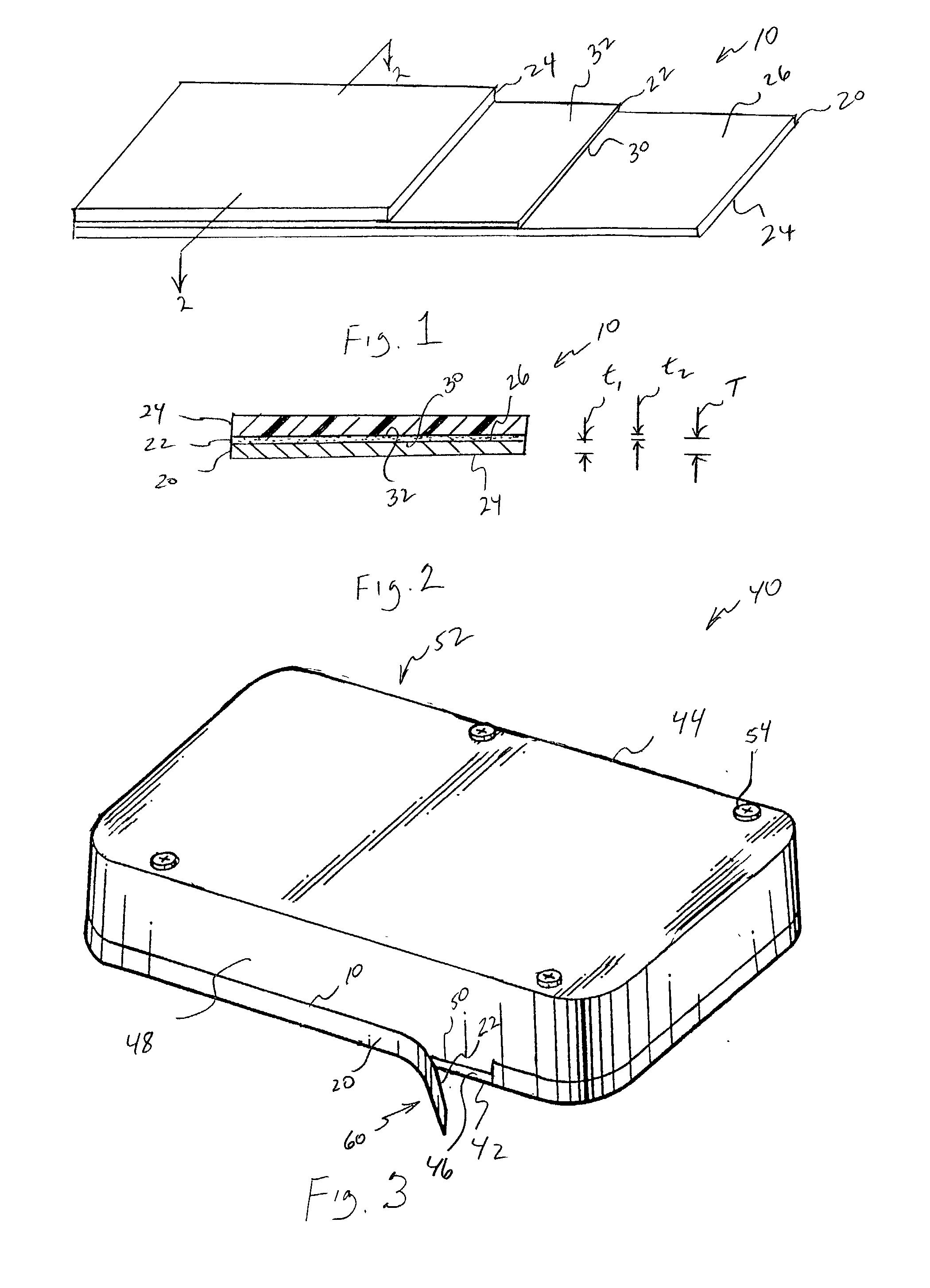
[0012] In use, the tape may be applied manually or using automated equipment to cover a seam, which may be internal or external, between adjoining parts, such as between a base and a cover of a housing or other enclosure for an electronic device. In this regard, with the PSA surface of the tape being bonded across the seam to each of the adjoining housing parts, electrical continuity may be provided across the seam for the EMI shielding of the device. The tape also may provide environmental sealing of the housing from dust and other contaminants. Advantageously, however, the adhesive is formulated to be cleanly releasable from the surfaces of the housing parts, which may be formed of a metal such as steel, aluminum, or magnesium, metal-plated, or of a plastic or other polymeric material which is loaded with a metal or other electrically-conductive filler or which is provided with a metal, metal-filled, or other conductive layer. By "cleanly releasable," it is meant that the tape may be removed from the housing surfaces under a moderate peel force of about 1-10 lb / in (179-1790 g / cm) while exhibiting a primarily adhesive failure from those surfaces so as to leave substantially no adhesive residue thereon.

Problems solved by technology

It is believed, however, that the EMI shielding tapes heretofore employed in the sealing of housings for disk drives and other electronic devices have not been considered to be removable or repositionable.
That is, upon being removed for repair, rework, or other disassembly of the drive, the tapes did not release cleanly from the surfaces of the housing parts, but instead, whether as a result of initial adhesion or a build on aging, left an adhesive residue thereon.

Method used


Image

  • Clean release tape for EMI shielding
  • Clean release tape for EMI shielding

Examples


Embodiment Construction

[0041] A layer of a solvent-based, acrylic PSA filled with conductive particles was coated at a thickness of about 2 mils (0.05 mm) onto one side of several strips of 2 mil (0.05 mm) thick aluminum foil. The samples so prepared were adhered using an applied pressure obtained by rolling with a 10 pound (4.5 kg) roller at 12 in / min (30.5 cm / min) once in each lengthwise direction onto stainless steel substrates for 180.degree. peel (PSTC-1) and shear (PSTC-7) adhesion testing. The peel testing was performed at increasing dwell times and at elevated temperatures. The peel adhesion results are shown in Table 1 and the shear adhesion results are shown in Table 2, with the letter "A" in each table denoting an adhesive failure to the substrate, i.e., a "clean break," and the letter "C" denoting a cohesive failure within the adhesive layer, i.e., a non-clean break as would be shown by adhesive residue on the substrate. For purposes of comparison, the results for a comparable conventional, no...


PUM

PropertyMeasurementUnit
frequencyaaaaaaaaaa
frequencyaaaaaaaaaa
EMI shielding effectivenessaaaaaaaaaa

Abstract

An EMI shielding tape adherable to a surface of a structure. The tape includes a backing layer, and an adhesive layer carried on at least one side of the backing layer. The adhesive layer has an inner face bonded the backing layer, and an opposite outer face which is bondable under pressure to the structure surface to adhere the tape thereto. The adhesive layer is formulated as an admixture of a pressure sensitive adhesive (PSA) composition and one or more electrically-conductive particulate fillers. When adhered to the structure surface, the tape is substantially cleanly releasable therefrom.

Description

CROSS-REFERENCE TO RELATED CASES[0001] The present application claims the benefit of the filing date of U.S. Provisional Application Serial No. 60 / 312,307; filed Aug. 14, 2001, the disclosure of which is expressly incorporated herein by reference.[0002] The present invention relates broadly to electrically-conductive, pressure-sensitive adhesive tapes for providing electromagnetic interference (EMI) shielding and dust or other environmental sealing of seams along cases, housing, and other enclosures for electronic devices, and particularly to a tape which is cleanly releasable to be removable and / or repositionable for allowing access to the interior of the enclosure for rework, repair, or other disassembly, and for allowing reassembly without the need to clean adhesive residue from the seam.[0003] The operation of electronic devices such as televisions, radios, computers, medical instruments, business machines, communications equipment, and the like is attended by the generation of ...

Claims


Application Information

Patent Timeline
Patent Type & Authority Applications(United States)
IPC IPC(8): C09J7/28C09J9/02H05K9/00
CPCC09J7/0207C09J7/0292C09J9/02Y10T428/14H05K9/0015Y10T428/19C09J2201/602C09J7/38C09J7/28C09J2301/314
Inventor JONES, PETERWRIGHT, DEANNA J.MALIK, ROBERT J.
Owner PARKER HANNIFIN CORP
Learn More