
Solar distillation unit

Inactive Publication Date: 2003-03-27
LUDWIG DAVID M
View PDF0 Cites 4 Cited by
  • Summary
  • Abstract
  • Description
  • Claims
  • Application Information

AI Technical Summary

Benefits of technology

[0016] It is another object of the present invention to provide an apparatus for distilling water using solar energy and a method for use thereof that increase energy and distillation efficiency.
[0023] It is still another object of the present invention to provide an apparatus for distilling water using solar energy and a method for use thereof that promote and maintain good health.

Problems solved by technology

It is common experience that tap water in many areas of the world where water is not plentiful may contain high concentrations of contaminants that make the water taste bad as well as, potentially, pose health risks.
It is also increasingly appreciated that people should drink a substantial amount of pure water, and this is one of the reasons for the popularity of bottled water, which people enjoy but which has the obvious disadvantage that it is expensive.
Bottled water has also been found to be inconsistent in quality.
There are some important problems with these known apparatus.
A reflector or concentrator adds significant cost and complexity, and becomes less useful over time as condensation forms on the reflector or concentrator, inevitably bringing with it some contamination from the atmosphere into the apparatus.
This contamination decreases the reflectivity or transmissivity of the reflector or concentrator.
However, the resulting lack of ventilation may hasten the growth of bacteria, fungus and algae in the apparatus, which detracts from the capability of the apparatus to heat the water and to provide the water in a condition that is safe and pleasant to drink.
Further, volatile components in the water are not permitted to escape the apparatus when it is relatively airtight.
Moreover, the materials of which the apparatus is formed may introduce contaminants themselves, such as by outgassing, or by corrosion or degradation as a result of contact with the water or exposure to radiation from the sun and elements and charged particles in the atmosphere.
Because of these shortcomings, the requirements for an optimally effective water distilling apparatus have to be stringent and are hard to achieve.

Method used


Image

  • Solar distillation unit
  • Solar distillation unit
  • Solar distillation unit

Examples


Embodiment Construction

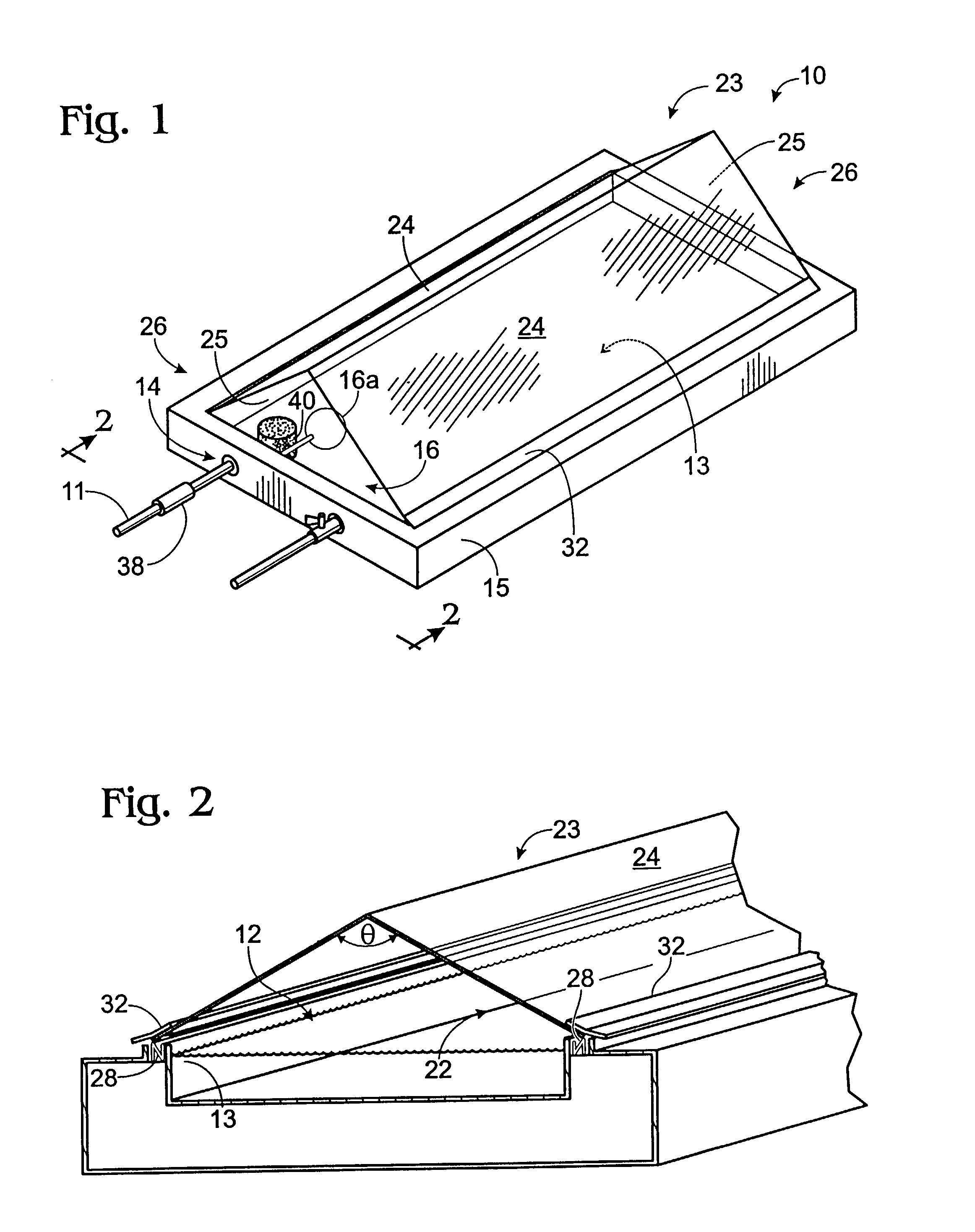
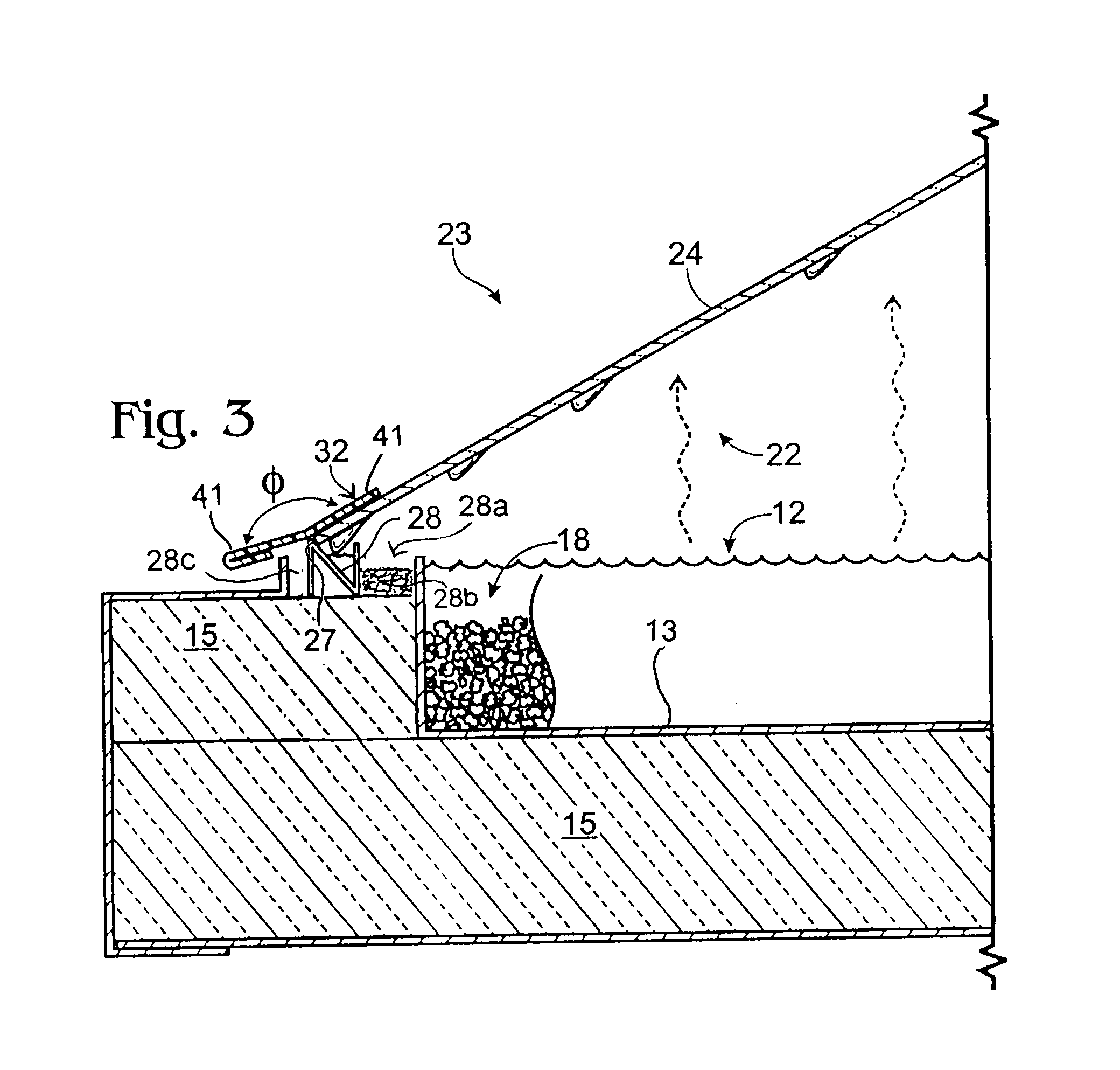
[0033] The heart of this invention is in the novel combination of features and materials that provide efficient operation and improved durability of performance even under harsh climatic conditions. All materials are selected to prevent corrosion, deterioration, formation of permanent deposits on the heat absorbing medium, and propagation of biological contamination into the water produced by the solar distillation unit. In addition, the particular geometry of the unit is selected to improve evaporation efficiency, maintenance-free cleanliness of the apparatus, and long-lasting yield of high quality water with minimal variation due to ambient conditions.

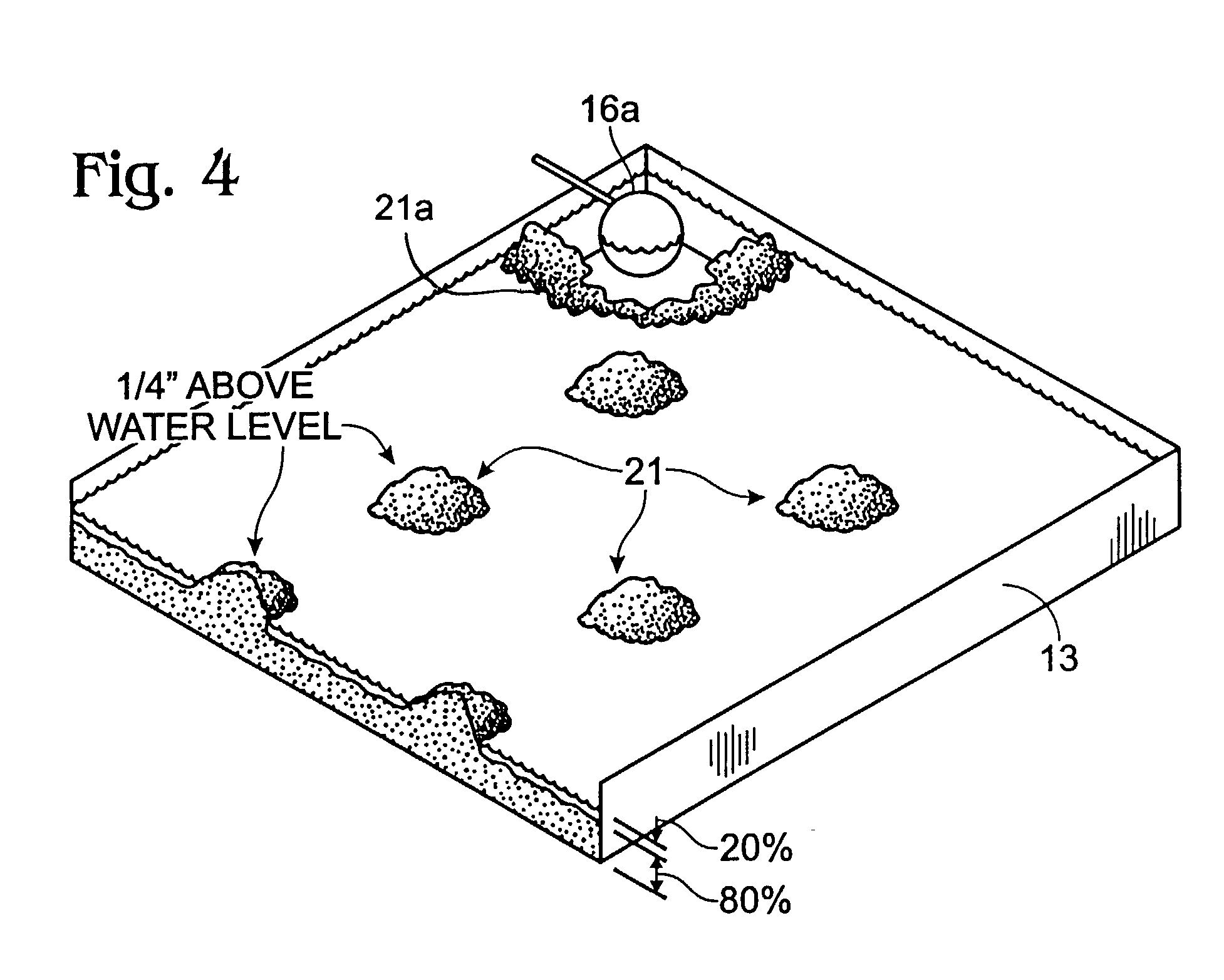
[0034] Referring to FIGS. 1 and 2, a preferred apparatus 10 for distilling water using solar energy according to the present invention is shown. The apparatus 10 includes a water-holding stainless steel container defining a volume 12 for receiving water to be distilled. The container is preferably in the form of a tray 13 and the wat...


PUM

PropertyMeasurementUnit
Fractionaaaaaaaaaa
Angleaaaaaaaaaa
Diameteraaaaaaaaaa

Abstract

A solar distilling apparatus employs anthracite coal as a heat-absorbing medium. Greenhouse roof elements rest over a gutter that is isolated from the water-holding container to prevent deposit formation and algae growth from reaching the gutter. Bacterial growth is inhibited by ventilation and the use of titanium-laden magnetite mixed with the anthracite particles. The gutter is also isolated from the exterior of the unit, which prevents contamination from outside sources. The exterior side of the roof elements resting on the gutter are fitted with a metal skirt that provides a heat sink preventing the re-evaporation of condensation flowing toward the gutter.

Description

[0001] This application is based on U.S. Ser. No. 09 / 589,138, filed Jun. 7, 2000, which was based on U.S. Provisional Serial No. 60 / 174,341, filed Jan. 4, 2000.[0002] 1. Field of the Invention[0003] The present invention relates to an apparatus for distilling water using solar energy and method for use thereof, particularly to provide hot or cold water for irrigation and drinking.[0004] 2. Description of the Related Art[0005] The need for treating water to make it safe and satisfying for human needs, particularly for drinking, is easily appreciated. It is common experience that tap water in many areas of the world where water is not plentiful may contain high concentrations of contaminants that make the water taste bad as well as, potentially, pose health risks. It is also increasingly appreciated that people should drink a substantial amount of pure water, and this is one of the reasons for the popularity of bottled water, which people enjoy but which has the obvious disadvantage t...

Claims


Application Information

Patent Timeline
IPC IPC(8): B01D5/00C02F1/14
CPCB01D5/0066C02F1/14C02F2209/42Y10S203/01Y10S159/15Y10S159/903Y02A20/212
Inventor LUDWIG, DAVID M.
Owner LUDWIG DAVID M
Learn More