
Liquid crystal panel, manufacturing method therefor, and electronic equipment

a technology of liquid crystal panels and manufacturing methods, applied in non-linear optics, instruments, optics, etc., can solve the problems of reducing productivity, unable to always be adopted, and the wiring formed on both substrates cannot bring into vertical conduction with each other

Inactive Publication Date: 2003-03-20
SEIKO EPSON CORP
View PDF5 Cites 55 Cited by
  • Summary
  • Abstract
  • Description
  • Claims
  • Application Information

AI Technical Summary

Benefits of technology

[0010] According to this liquid crystal panel, all of the first wiring and the second wiring are brought into vertical conduction with reliability regardless of the position of the liquid crystal injection hole formed in the sealing material. That is, for example, when the wiring which are not vertically conductively connected by the conducting particles dispersed in the sealing material, such as wiring which reach the portion where the sealing material is omitted to form the liquid crystal injection hole, and the wiring which are not always brought into adequate vertical conduction by the conducting particles dispersed in the sealing material, such as wiring which reach the neighborhood of the liquid crystal injection hole, vertical conduction is achieved with reliability by the conducting particles dispersed in the vertical conduction portion. That is, in the liquid crystal panel according to the present invention, even when the liquid crystal injection hole is formed along the edge of the sealing material, which is also used for vertical conduction, the first wiring and the second wiring can be brought into vertical conduction with reliability.
[0016] When the aforementioned vertical conduction portion is made of the same material as that of the aforementioned sealing material, since the vertical conduction portion can be formed concurrently during the sealing material formation step, simplification of the manufacturing step and reduction of manufacturing costs can be achieved. In order to achieve vertical conduction with reliability through the conducting particles dispersed in the sealing material and the vertical conduction portion, it is desirable that the widths of the portions of the facing the aforementioned sealing material or vertical conduction portion plurality of first wiring and the plurality of second wiring are made larger than the widths of the other portions of the first and second wiring.
[0019] In order to overcome the aforementioned problems, electronic apparatus according to the present invention is provided with the aforementioned liquid crystal panel. As described above, by the liquid crystal panel according to the present invention, the first wiring and the second wiring can be brought into conduction with reliability regardless of the position of the liquid crystal injection hole. Consequently, according to the electronic apparatus provided with this liquid crystal panel, failures in vertical conduction is suppressed and, therefore, excellent display quality is realized.
[0020] A manufacturing method for a liquid crystal panel according to the present invention is a method in which a first substrate having a plurality of first wiring and a second substrate having a plurality of second wiring are adhered with a sealing material therebetween, a liquid crystal is injected between both substrates through the liquid crystal injection hole formed in the sealing material and, therefore, the liquid crystal panel is manufactured, and includes the steps of forming the sealing material with conducting particles therein and interposing the sealing material in the portion, at which the aforementioned plurality of first wiring and the aforementioned plurality of second wiring face each other, on the aforementioned first substrate or the aforementioned second substrate, forming a vertical conduction portion in the neighborhood of (i.e., adjacent) the aforementioned liquid crystal injection hole and in a region surrounded by the aforementioned sealing material, the vertical conduction portion including conducting particles dispersed therein, at which the aforementioned plurality of first wiring and the aforementioned plurality of second wiring face each other and adhering the aforementioned first substrate and the aforementioned second substrate with the aforementioned sealing material and the aforementioned vertical conduction portion therebetween. According to the liquid crystal panel produced by this method, since vertical conduction of the wiring can be achieved by not only the sealing material, but also the vertical conduction portion, conduction failure can be effectively suppressed.
[0022] According to this manufacturing method as well, effects similar to those in the aforementioned manufacturing method are achieved. Furthermore, according to the present manufacturing method, since the plurality of third wiring in the second substrate region are connected to each other by the common wiring before portioning into individual liquid crystal cells, there is an advantage that electrostatic discharge damage to the two-terminal type nonlinear element is prevented. These third wiring are partitioned on a liquid crystal cell basis and, at the same time, are partitioned electrically. Consequently, in order to prevent the electrostatic discharge damage to the two-terminal type nonlinear element during the step of injecting the liquid crystal into the liquid crystal cell, a plurality of liquid crystal cells have to be joined to each other in the extension direction of the third wiring before being subjected to this step. In consideration of these circumstances, it can be said that the position, at which the liquid crystal injection hole is to be formed, is desirably not in the edge orthogonal to the extension direction of the third wiring of the sealing material, but in the edge parallel to the extension direction of the third wiring. On the other hand, the edge parallel to the extension direction of the third wiring of the sealing material is the edge to be used for vertical conduction between the first wiring and the second wiring. Herein, in the present invention, since vertical conduction between the first wiring and the second wiring is achieved by the vertical conduction portion in addition to the sealing material, there is an advantage in that even the wiring which cannot be brought into vertical conduction by the sealing material because the sealing material terminates at the liquid crystal injection hole, vertical conduction can be achieved with reliability by the vertical conduction portion.
[0023] In these manufacturing methods, it is desirable that the aforementioned sealing material and the vertical conduction portion are formed in a single step from the same material. According to this, simplification of the manufacturing step and reduction of the manufacturing cost can be achieved.

Problems solved by technology

This is because the conducting particles cannot be placed in the portion corresponding to the liquid crystal injection hole between both substrates, and the wiring formed on both substrates cannot be brought into vertical conduction with each other.
However, when the positions of the liquid crystal injection holes are restricted accompanying adoption of vertical conduction, the configuration, in which the liquid crystal injection holes are formed while being aligned on one of the sides with respect to all liquid crystal cells, cannot always be adopted.
As a result, a reduction of productivity may occur.
On the other hand, among the plurality of first wiring or the plurality of second wiring, even when the wiring have a portion facing the wiring of the other with the sealing material therebetween, regarding the wiring, the end portions of which have reached the neighborhood of the liquid crystal injection hole, it is also considered that the area facing the sealing material (that is, the area of the portion which becomes a target for vertical conduction by the conducting particles in the sealing material) may not be ensured adequately.
In particular, for example, when the sealing material is formed using a printing technique, since the deviation of the position of formation thereof is relatively large, such a problem may become more pronounced.
In other words, a wiring which extends to a location immediately adjacent the liquid crystal injection hole may not receive adequate conductive sealing material to ensure reliable conductive connectability.
On the other hand, if the vertical conduction portion is installed integrally with the sealing material (so that it is joined to the sealing material), the flow of the liquid crystal may become stagnant at the joint portion and, therefore, the liquid crystal may not be quickly injected into the liquid crystal cell.

Method used


Image

  • Liquid crystal panel, manufacturing method therefor, and electronic equipment
  • Liquid crystal panel, manufacturing method therefor, and electronic equipment
  • Liquid crystal panel, manufacturing method therefor, and electronic equipment

Examples


Embodiment Construction

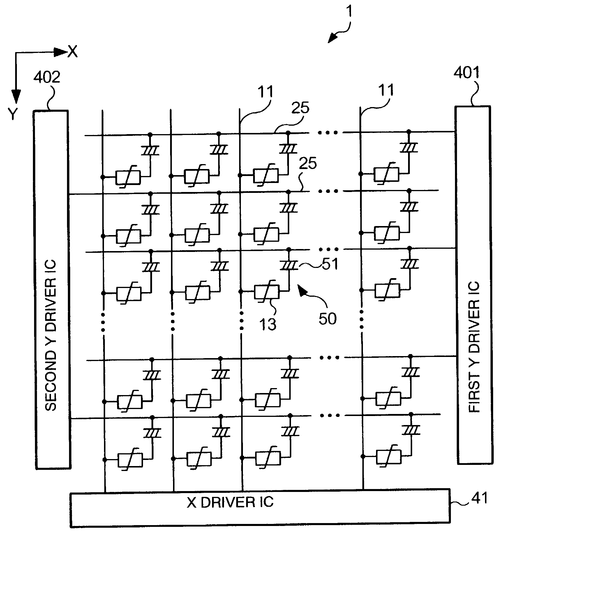
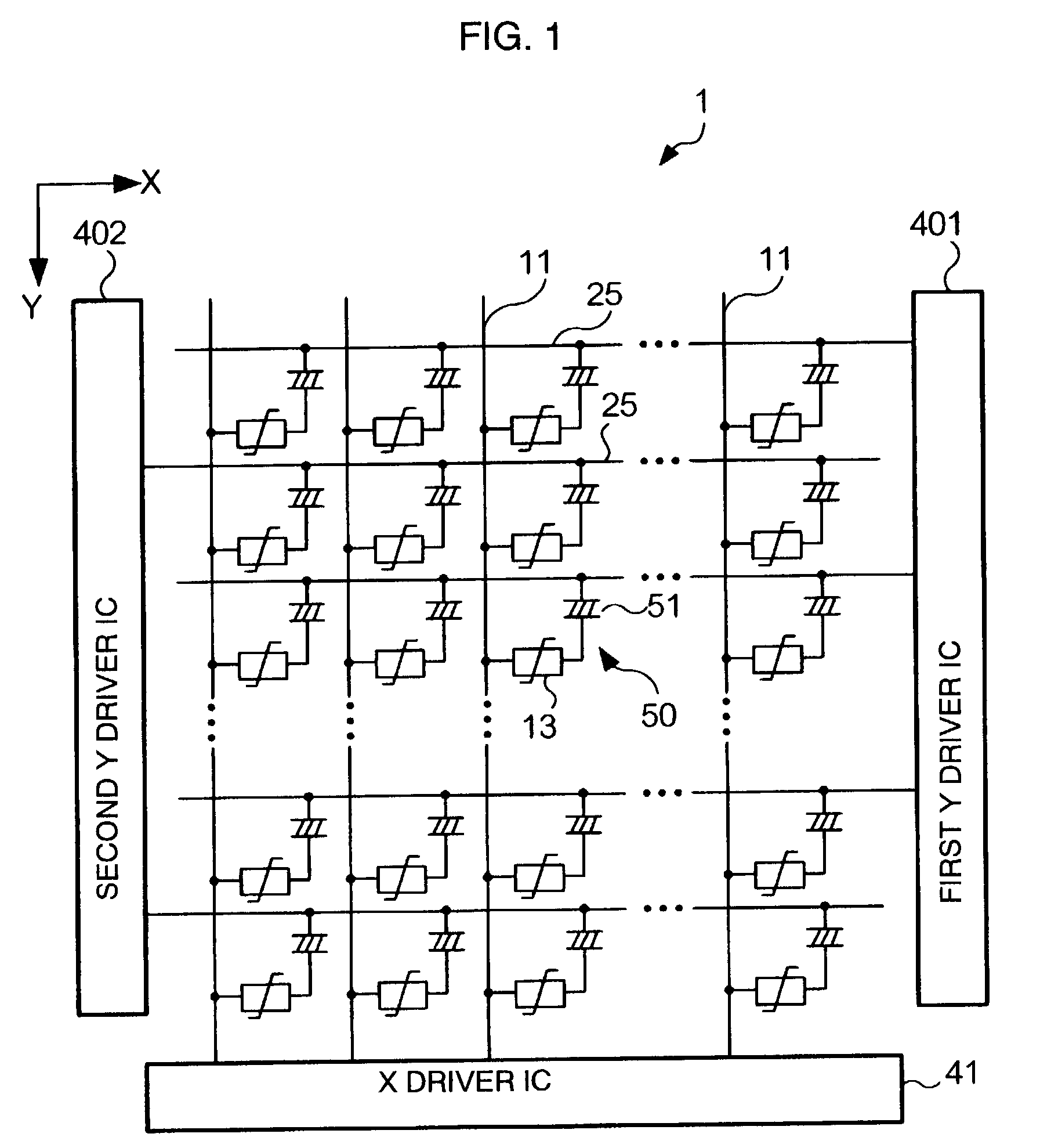
[0092] In the aforementioned embodiment, the scanning line 25, which reached the neighborhood of the liquid crystal injection hole 30a and which did not overlap the sealing material 30 was assumed to be one line. However, it is needless to say that the number of lines may be equivalent to or more than this. That is, when a plurality of scanning lines 25 reach the neighborhood of the liquid crystal injection hole 30a and do not overlap the sealing material 30, it is essential only that the vertical conduction portion 37 is installed in order to overlap all of these scanning lines 25.

[0093] In the aforementioned embodiment, the vertical conduction portion 37 was installed in order to face not only the scanning line 25, which reached the liquid crystal injection hole 30a and which did not have a portion facing the sealing material 30, but also the scanning lines 25 adjacent thereto, that is, the scanning lines 25 having a portion facing the sealing material 30. However, the scanning li...


PUM

PropertyMeasurementUnit
vertical conductionaaaaaaaaaa
widthsaaaaaaaaaa
vertical conductiveaaaaaaaaaa

Abstract

A liquid crystal panel 1 has a configuration in which an element substrate 10 including routing wiring 16 and a counter substrate 20 including scanning lines 25 are adhered with a sealing material 30 therebetween and, in addition, a liquid crystal is injected between both substrates through a liquid crystal injection hole 30a formed in the sealing material 30. The scanning lines 25 are brought into conduction with the routing wiring 16 through conducting particles 32 dispersed in the sealing material 30. However, the scanning lines 25, which have end portions reaching the neighborhood of the liquid crystal injection hole 30a, among the plurality of scanning lines 25, are brought into conduction with the routing wiring 16 through conducting particles 32 dispersed in a vertical conduction portion 37 or through the conducting particles 32 in both the sealing material 30 and the vertical conduction portion 37.

Description

[0001] 1. Technical Field of the Invention[0002] The present invention relates to a liquid crystal panel, a manufacturing method therefor, and electronic equipment using the liquid crystal panel.[0003] 2. Description of the Related Art[0004] It is generally known that the liquid crystal panel includes a liquid crystal between a pair of substrates adhered with a sealing material therebetween. In such a sort of liquid crystal panel, an electrode is formed on the surface facing the other substrate among individual substrates. A voltage in accordance with the image to be displayed is applied to this electrode through a routing wiring connected to the electrode.[0005] Furthermore, a configuration in which the routing wiring connected to the electrodes of both substrates have been formed intensively on one substrate has also been suggested. That is, in this configuration, the electrode formed on the one substrate is connected to the routing wiring formed on the other substrate through, fo...

Claims


Application Information

Patent Timeline
Patent Type & Authority Applications(United States)
IPC IPC(8): G02F1/1339G02F1/1341G02F1/1345G02F1/1365
CPCG02F1/1339G02F1/1341G02F1/1345G02F2001/13456G02F1/13456
Inventor KANEKO, HIDEKIYAMAGUCHI, YOSHIONOMURA, KIMIHIROTANAKA, CHIHIROKAMIJIMA, MOTOHIRO
Owner SEIKO EPSON CORP
Learn More