Conjugated polycarbazole derivatives in Organic Light Emitting Diodes
a technology of organic light-emitting diodes and conjugated polycarbazoles, which is applied in the field of optical instruments, can solve the problems of poor vision angle, low efficiency, and speed and temperature range limitations, and none of them meet all
- Summary
- Abstract
- Description
- Claims
- Application Information
AI Technical Summary
Problems solved by technology
Method used
Image
Examples
first embodiment
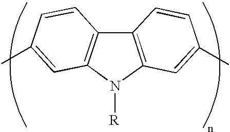
[0034] In the invention, shown in FIG. 3, an OLED was fabricated consisting of an Indium Tin Oxide transparent conductive anode on a glass substrate, a thin LiF layer to promote hole injection, a blend of PEHC (poly(N-ethylhexyl)-2,7-carbazole) and TPD (N,N'-diphenyl-N,N'-bis(3-methylphenyl)-1,1'-biphenyl-4,4'-diamine) as the hole transport layer and emitter, Bu-PBD (2-(4-biphenylyl)-5-(4-tert--butylphenyl)-1,3,4-oxadiazole) as the electron transport layer, a thin LiF layer to promote electron injection, and an Al cathode. The blend of PEHC and TPD is solubilized in chloroform:toluene in a ratio of 9.8:0.2, and spin-coated. PBD, LiF and Al layers were thermally evaporated.
[0035] The diode produces the electroluminescence spectrum (curve 2) shown in FIG. 4, compared with the photoluminescence spectrum (curve 1) of PEHC in the solid state.
[0036] Both spectra seem to show a maximum of emission at similar wavelengths, i.e. in the blue range, with two peaks around 437 nm and 453 nm. The ...
second example
[0038] In a second embodiment of the invention shown in FIG. 6, an OLED was fabricated consisting of an Indium Tin Oxide transparent conductive anode on a glass substrate, a first thin LiF layer to promote hole injection, a POC (poly(N-octyl-2,7-carbazole)) for the hole transport layer, Bu-PBD (2-(4-biphenylyl)-5-(4-tert-butylphenyl)-1,3,4-oxadiazole) as the electron transport layer, a second thin LiF layer to promote electron injection, and an Al cathode.
[0039] FIG. 7 shows that the resulting diode emits blue light with emission peaks around 423 and 447 nm (shoulder), with another weak shoulder around 480 nm, for photoluminescence (curve 4) and electroluminescence (curve 5). The peaks are slightly shifted towards higher wavelengths for the electroluminescence, but no excimer is observed. This small shift and broadening of the peaks could be due to the cavity effect when an excess of electrons is injected on the molecule, or to an increased radiative decay from longer conjugated seg...
third example
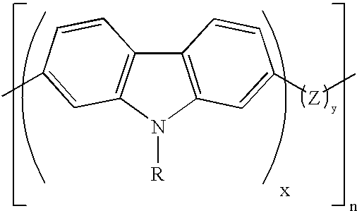
[0042] In a third embodiment of the invention, an OLED was fabricated consisting of an Indium Tin Oxide transparent conductive anode on a glass substrate, a thin LiF layer to promote hole injection, a blend of P(OCDOF) (poly(N-octyl-2,7-carbazole-alt-9,9'-dioctyl-2,7-fluorene) and TPD (N,N'-diphenyl-N,N'-bis(3-methylphenyl)-1,1'-biphenyl-4,4'-diamine) as the hole transport layer and emitter, Bu-PBD (2-(4-biphenylyl)-5-(4-te-rt-butylphenyl)-1,3,4-oxidiazole) as the electron transport layer, a thin LiF layer to promote electron injection, and an Al cathode. See FIG. 8. The blend of P(OCDOF) and TPD is solubilized in chloroform:toluene in a ration of 9.8:0.2, and spin-coated. PBD, LiF and Al layers are thermally evaporated.
[0043] The diode produces the electroluminescence spectrum (curve 7) shown in FIG. 9, compared with the photoluminescence spectrum (curve 6) of P(OCDOF) in the solid state.
[0044] Both spectra seem to show a maximum of emission at similar wavelengths, i.e. in the blue...
PUM
| Property | Measurement | Unit |
|---|---|---|
| glass transition temperature | aaaaa | aaaaa |
| wavelengths | aaaaa | aaaaa |
| wavelengths | aaaaa | aaaaa |
Abstract
Description
Claims
Application Information
 - R&D Engineer
- R&D Manager
- IP Professional
- Industry Leading Data Capabilities
- Powerful AI technology
- Patent DNA Extraction
Browse by: Latest US Patents, China's latest patents, Technical Efficacy Thesaurus, Application Domain, Technology Topic, Popular Technical Reports.
© 2024 PatSnap. All rights reserved.Legal|Privacy policy|Modern Slavery Act Transparency Statement|Sitemap|About US| Contact US: help@patsnap.com


