
Optical sampling using intermediate second harmonic frequency generation

a second harmonic and frequency generation technology, applied in the field of optical sampling using intermediate second harmonic frequency generation, can solve the problems of unsatisfactory high background noise, and increased need

Inactive Publication Date: 2003-01-09
AGILENT TECH INC
View PDF1 Cites 17 Cited by
  • Summary
  • Abstract
  • Description
  • Claims
  • Application Information

AI Technical Summary

Benefits of technology

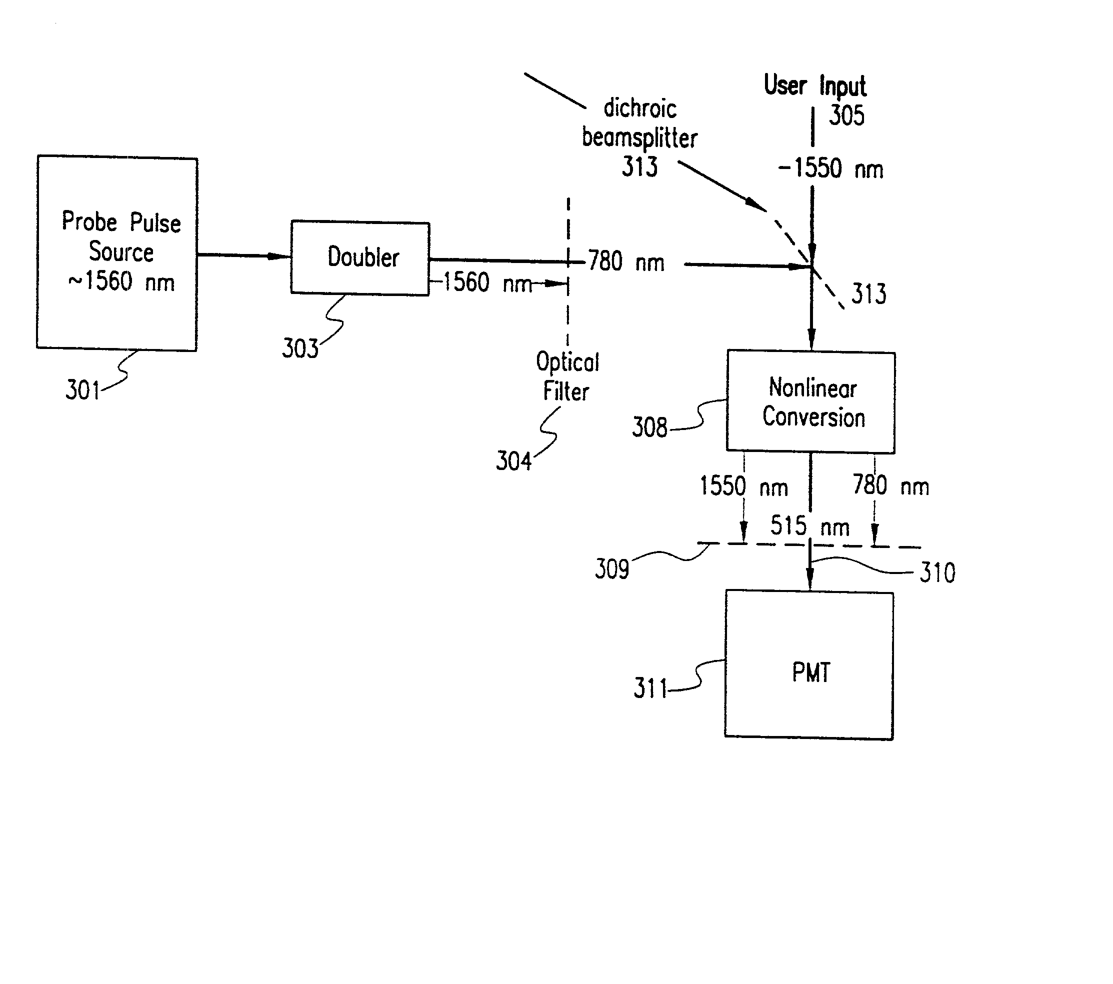
[0017] Preferably, the probe pulse source comprises a passive mode-locked fiber ring laser (or, alternatively, an active mode-locked fiber ring laser), and the step of processing comprises using an analog-to-digital converter (ADC) to obtain high-speed processed sampled signals, the method further including microprocessor control and analysis. At least one advantage of the present scheme is that if a pedestal (low DC light level with a higher power spike) is present on the 1550 nm probe signal, it is considerably reduced after the second harmonic generation. This improves the dynamic range of the measurement system.
[0018] Optionally, the invention includes the step of achieving at least 50% conversion efficiency in obtaining the near third harmonic signal, and includes the step of narrowing pulse width of pulse source signals, giving greater system bandwidth.

Problems solved by technology

SFG methods of optical sampling might result in undesirably high background noise.
Higher pump powers for optical sampling systems are desirable, but result in greater need to eliminate background noise, because background noise increases as the square of the probe intensity.
When optical mixing is used as the sampling mechanism, the resulting "background noise" is highly undesirable.
Presently, most optical sampling schemes other than those based on series connected photo-conductive switches (PCS's) have an associated background noise problem.
However, in most instances the input signals to be sampled also fall in the same 1550 nm wavelength band, which makes it difficult to distinguish the input signals from the probe or sampling pulse signals, compounding the background noise problem and, complicating the measurement system design.
By simply using SFG and mixing the incoming signals with the user input signals, the background noise is not automatically reduced to acceptable levels.
Resorting to SFG techniques, because of the close proximity between the wavelength ranges of the signal to be measured and the probe signal, it is difficult to design an optical bandpass filter.

Method used


Image

  • Optical sampling using intermediate second harmonic frequency generation
  • Optical sampling using intermediate second harmonic frequency generation
  • Optical sampling using intermediate second harmonic frequency generation

Examples


Embodiment Construction

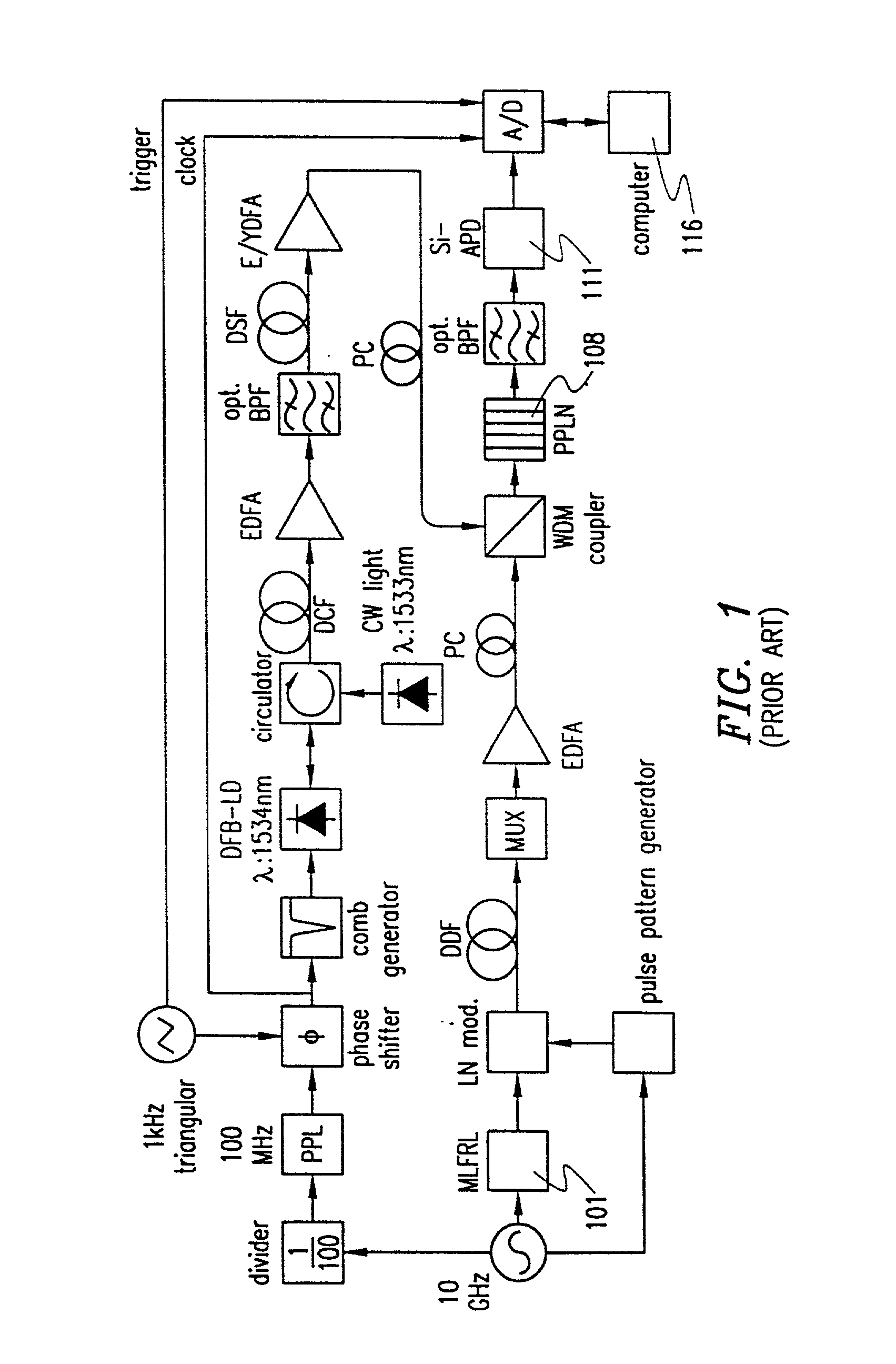
[0033] FIG. 1 shows a prior art experimental setup for producing SFG by using a 1.4 mm thick PPLN crystal as the SFG material instead of a KTP crystal or a conventional 10 mm thick PPLN crystal. A mode-locked fiber ring-laser (MLFRL) generates optical signal pulses at 10 GHz repetition rate. The optical signal pulses are modulated by a LiNbO.sub.3 modulator (LN mod.) to a 10 Gbit / s optical signal, and its pulsewidth is compressed from 4.9 to 1.3 ps in a dispersion-decreasing fiber (DDF). The modulated and compressed optical signal is time-division-multiplexed to a 160 Gbit / s optical signal by using an optical multiplexer (MUX) consisting of four split-relatively-delay-and-recombine fiber doublers.

[0034] The optical sampling pulses are generated by a gain-switched distributed-feedback laser diode (DFB-LD) with a repetition rate of 100 MHz. The timing jitter of the gain-switched optical pulses is reduced to 160 fs by using a continuous wave (CW) light-seeding method. These pulses are ...


PUM

PropertyMeasurementUnit
wavelength rangeaaaaaaaaaa
lengthaaaaaaaaaa

Abstract

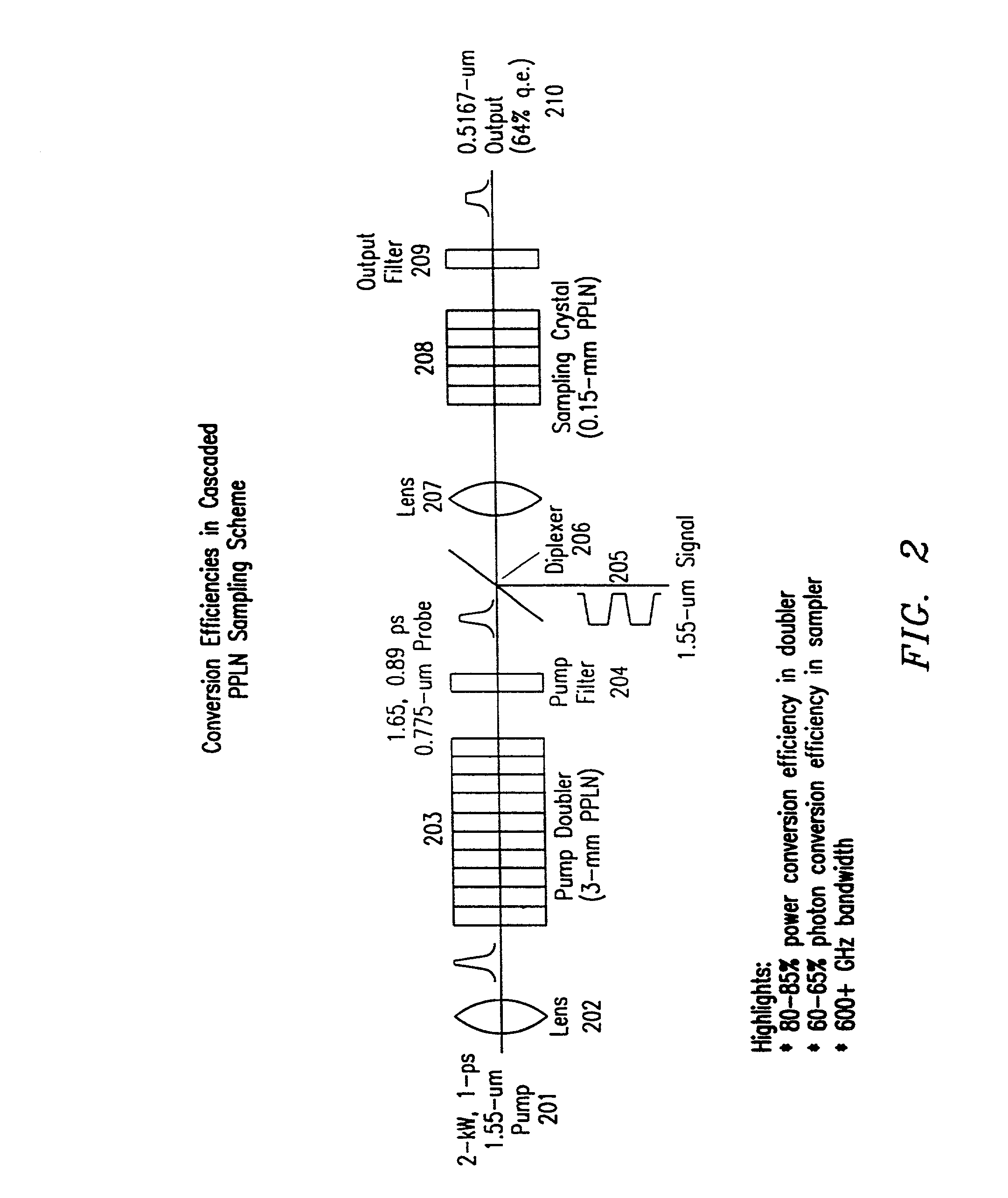
An optical sampling method and apparatus use a probe pulse source of a predetermined optical wavelength range, e.g., 1560 nm, to sample incoming optical pulses in approximately the same wavelength range. The probe pulse source is frequency-doubled e.g., using a frequency doubler such as a nonlinear PPLN crystal, to obtain an intermediate second harmonic which may be filtered with a 780 nm bandpass filter to eliminate at least source frequency noise background. The filtered intermediate second harmonic is then mixed with the user input signal using an optional polarizing beam splitter and a dichroic beam splitter. The mixed signal is sent to a sum frequency generating (SFG) nonlinear crystal, e.g., a PPLN crystal, where the resulting frequency is near the third harmonic. The output from the SFG PPLN crystal may be filtered using a bandpass 515 nm filter to remove unwanted wavelengths and processed to measure / sense the near third harmonic content using a photomultiplier tube (PMT). Beyond the PMT, the output may be sent to a microprocessor for analysis and display on a cathode ray oscilloscope as necessary. 80-85% power conversion efficiency in the frequency doubler, a 60 or 65% photon conversion efficiency in the sampler and handling of 600+ GHz bandwidths, as well as background noise reduction are possible by using the invention.

Description

[0001] 1. Technical Field of the Invention[0002] This relates to an improved method and system for obtaining optical samples of good quality in optical communications.[0003] 2. Description of Related Art[0004] Optoelectronics technology and its applications are expanding with the result that integrated optics technology can be used with considerable advantages in communications. Optical modulators, switches, multiplexers are commonly employed by fabricating them both on single substrates of both dielectrics and semiconductors. For measuring the waveforms of optical pulses used in high bit rate optical communications, it is common practice and desirable to use optical sampling with high sensitivity and high time resolution. Optical sampling systems often use a probe signal and optical mixing with a user signal to achieve what is known as sum frequency generation (SFG) which is very useful for obtaining eye diagrams for sampled user signals. SFG methods of optical sampling might resul...

Claims


Application Information

Patent Timeline
Patent Type & Authority Applications(United States)
IPC IPC(8): G01J11/00G02F1/377H04B10/00H04B10/02H04B10/04H04B10/06H04B10/08H04B10/142H04B10/152H04B10/18
CPCH04B10/00
Inventor LEE, GREGORY S.JUNGERMAN, ROGER LEE
Owner AGILENT TECH INC
Learn More