
Spin-on filtering oil removal cartridge

a technology of spin-on filtering and oil removal cartridge, which is applied in the direction of filtration separation, separation process, braking system, etc., can solve the problems of difficult to contain oil, contaminated desiccant material housed in air dryer, elastomeric seals and seats of downstream components, and large draining capacity,

Inactive Publication Date: 2002-12-19
BENDIX COMML VEHICLE SYST LLC
View PDF0 Cites 9 Cited by
  • Summary
  • Abstract
  • Description
  • Claims
  • Application Information

AI Technical Summary

Benefits of technology

[0015] A primary benefit of the subject invention resides in the ease of removing and installing an oil removal cartridge in an air compressor system for a vehicle brake system.
[0017] Still another benefit of the subject invention resides in minimizing oil contamination of components downstream from an air compressor for a vehicle brake system.

Problems solved by technology

However, because oil is difficult to contain, it passes into the pressurized air stream exiting the compressor.
As a result, elastomeric seals and seats of downstream components, as well as the desiccant material housed within the air dryer, often become contaminated with the oil accompanying the pressurized air.
Moreover, a relatively large draining capacity is required since a considerable amount of the water vapor condenses to liquid water upon reaching the air dryer.
This, unfortunately, adds to the complexity and cost of the compressed air system.
Furthermore, water resulting from the condensed vapor has the potential to freeze.
Again, however, the addition of a heating element adds to the complexity and cost of the compressed air system.
To change the filter element, a user needs to disassemble the housing which is cumbersome and often requires the use of special tools.
Oftentimes, a sump needs to be emptied which creates the risk of liquids spilling and damaging the system.
These steps require considerable time and cause the removal and installation process to be rather complex.

Method used


Image

  • Spin-on filtering oil removal cartridge
  • Spin-on filtering oil removal cartridge
  • Spin-on filtering oil removal cartridge

Examples


Embodiment Construction

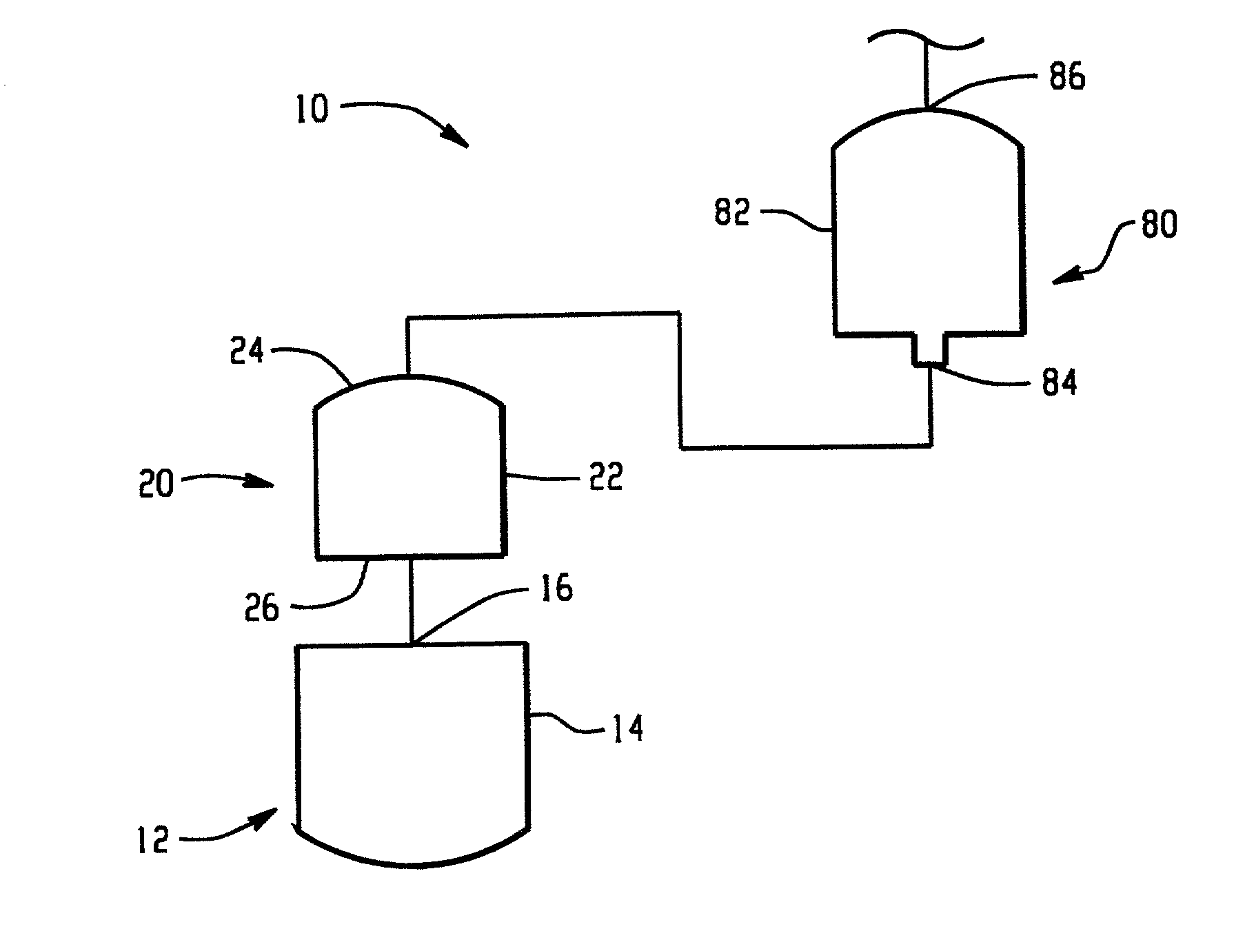
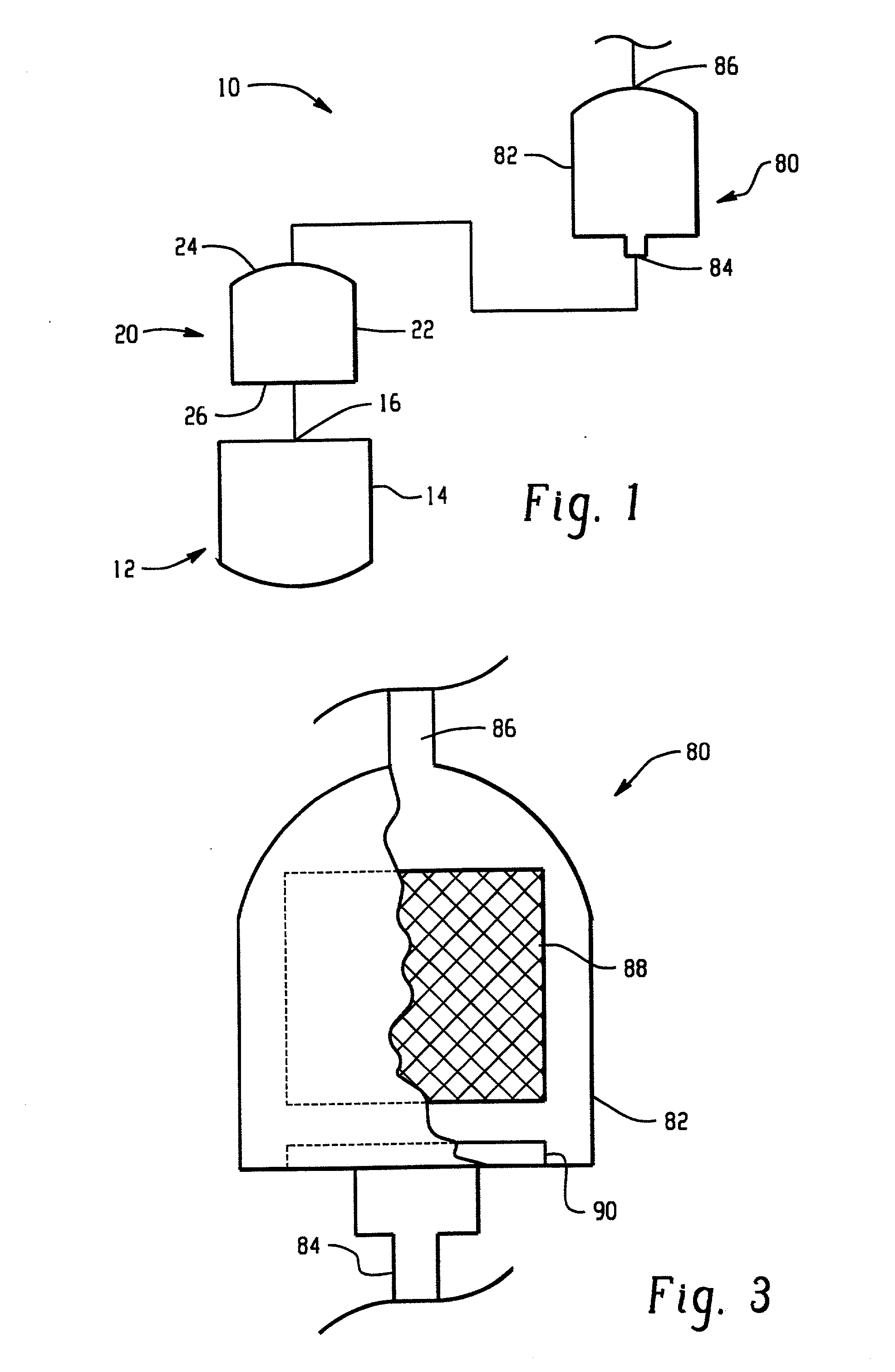
[0022] In FIG. 1, a compressed air system 10 for an air brake assembly is shown in accordance with the present invention. The compressed air system includes a compressor 12 having a crank case 14 which houses portions of the compressor. The compressor pressurizes air in a conventional manner, for example, by using a piston (not shown) slidable within a bore (not shown) of the crank case. Dynamic components of the compressor, such as a crank shaft and piston and bore, are lubricated with oil delivered from a vehicle engine or other means (not shown). Oil migrates into the pressurized air stream which exits the compressor through a port 16 of the compressor. Due to the relatively high operating temperature of the compressor, oil exiting the port is generally in the form of aerosols.

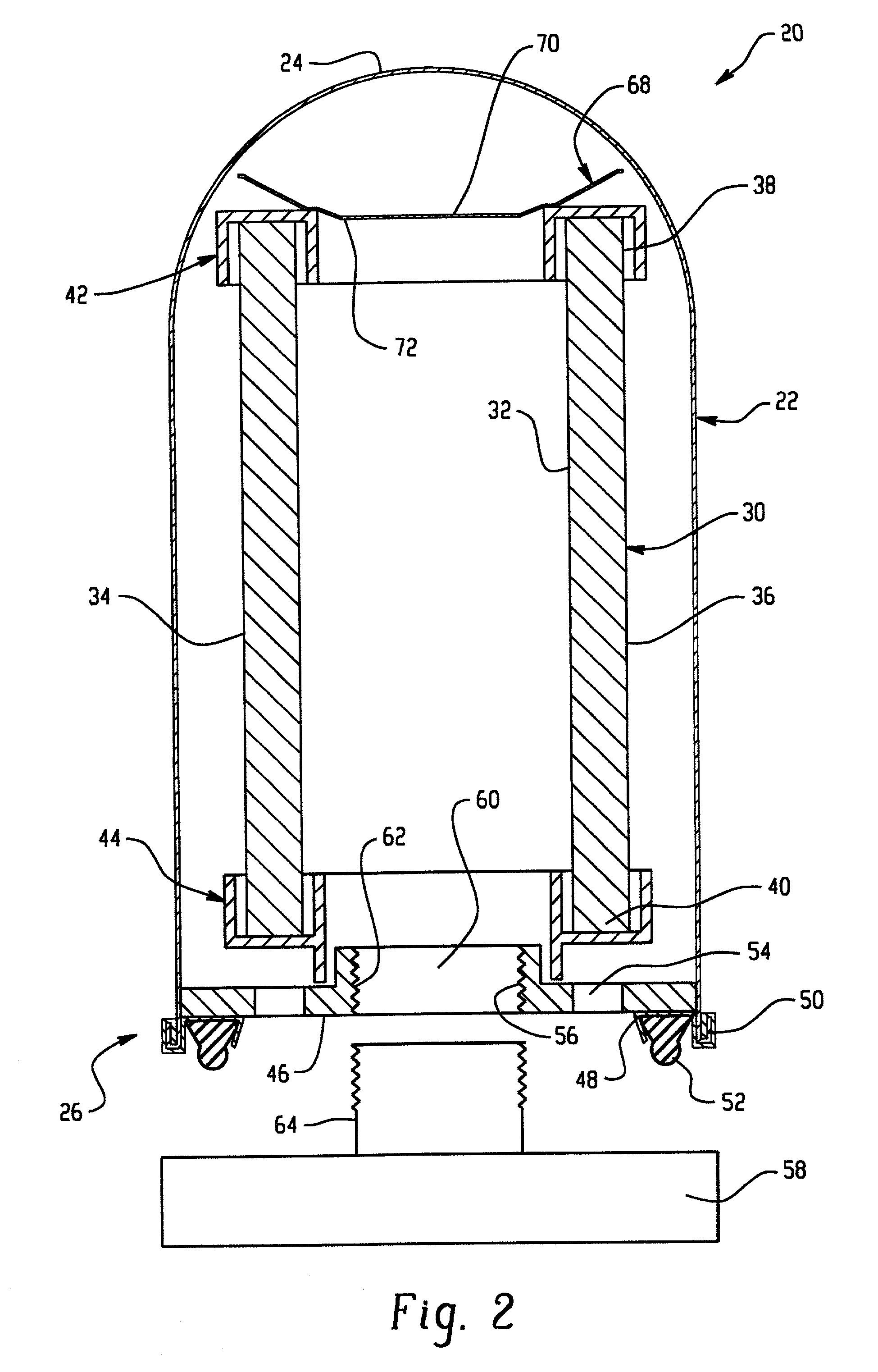
[0023] With reference also to FIG. 2, an oil removal cartridge 20 is disposed near the port of the compressor for removing oil from the compressed air stream. The oil removal cartridge includes an outer hou...


PUM

PropertyMeasurementUnit
diameteraaaaaaaaaa
forceaaaaaaaaaa
shapeaaaaaaaaaa

Abstract

A serviceable filtering oil removal cartridge for use in a compressed air assembly of a vehicle air brake system includes a housing having a first end and a second end. A filtering element is disposed within the housing for agglomerating and removing oil from compressed air entering the oil removal cartridge. A load plate is disposed within the housing for supporting the filtering element. The load plate includes a connecting portion dimensioned to allow the oil removal cartridge to be removed and installed as a single unit. The connecting portion is preferably a threaded annulus.

Description

[0001] 1. Field of the Invention[0002] The present invention relates to oil removal devices used in combination with compressed air, heavy vehicle braking systems. More particularly, this invention is directed to a spin-on filtering oil removal cartridge disposed downstream from an air brake compressor that is easy to assemble and install, and which is easily serviced.[0003] 2. Discussion of the Art[0004] Compressed air systems are used in brake systems to provide and maintain air under pressure to operate vehicle brakes and associated auxiliary air systems. Conventional systems include an air compressor for generating pressurized air and a drying device or air dryer disposed downstream from the compressor for removing entrained liquid from the air. The air dryer includes a desiccant material that removes water vapor from the air as it passes therethrough.[0005] As will also be appreciated, air brake compressors are typically supplied with oil from the vehicle engine in order to lub...

Claims


Application Information

Patent Timeline
Patent Type & Authority Applications(United States)
IPC IPC(8): B01D46/00B01D46/24B60T17/00
CPCB01D46/0015B01D46/003Y10S55/17B60T17/004B01D46/2411B60T17/00
Inventor FORNOF, WILLIAM P.KOENIG, JAMES P.
Owner BENDIX COMML VEHICLE SYST LLC
Learn More