Programmable radio frequency sub-system with integrated antennas and filters and wireless communication device using same

a radio frequency sub-system and integrated technology, applied in the direction of resonant antennas, substantially flat resonant elements, electromagnetic wave modulation, etc., can solve the problems of inability to meet the requirements of conventional antenna designs, imposed on the antenna of higher efficiency, and insufficient flexibility of the broader band and smaller size, etc., to achieve maximum flexibility, enhance user convenience, and enhance flexibility

Inactive Publication Date: 2002-12-05
E TENNA CORP
View PDF0 Cites 329 Cited by
  • Summary
  • Abstract
  • Description
  • Claims
  • Application Information

AI Technical Summary

Benefits of technology

[0056] The antenna control unit is configured in some embodiments to control both the transmit and receive antennas as well as their associated filters. In order to enhance flexibility, the antenna control unit in some embodiments may be configured according to different air interface standard specifications. This control unit embodiment may be combined with appropriately programmable embodiments of the transmit and receive antennas to operate with different air interface standards, on different frequency bands. Such a radio has maximum flexibility, enhancing user convenience by permitting universal operation.

Problems solved by technology

Typically, the antennas in present mobile phones and other devices are not very efficient, but they are sufficient to support current data rates of 9 to 12 kbps (kilobits per second) for voice communications.
These requirements imposed on the antenna of higher efficiency, broader band and smaller size tend to be in direct mutual conflict.
These requirements cannot be met with conventional antenna designs within the stringent form factors of wireless terminal aesthetics.
Of course, it is possible for a single antenna to cover all of these frequencies, but such an antenna would be too large to fit in or on a handset if its radiation efficiency were desired to approximate 100%.
By using lossy components in the construction of the antenna, we increase R.sub.L , which decreases efficiency.
Some losses also occur as the user holds a radiotelephone handset in the hand, next to the head, during a call.
There is much debate even today concerning how best to measure handset antenna efficiency, and currently no standard and widely accepted procedure for this measurement exists.
Adding resistive or mismatch losses will decrease this peak efficiency but increase the bandwidth on a one-for-one basis.
Finally, support of 700 MHz would not be feasible for this size of aperture.
However, to realize such a small aperture would require significant volume behind the antenna for the feed, transition and matching regions.
The non-ideal, real world situation, however, is much more complicated because the actual installation environment in the handset will absorb and reflect energy, thus affecting bandwidth.
Second; the efficiency is decreased.
The second effect, decreased efficiency, is the most problematic because, as the antenna is made smaller, it couples more tightly to its environment and it is harder to isolate from the causes of efficiency degradation.
The first is not possible because most sources will emit near their FCC limits.
The third is possible, but to a limited extent because an antenna that occupies a small fraction of a wavelength in size has a limited ability to achieve appreciable pattern gain or directivity.
The current state of the art for an internal antenna is a poor 5% efficiency (compared to 15% for an external stub, both cases for hand holding the phone next to a person's head).
However, all passive antennas are subject to a gain-bandwidth product limit.

Method used


Image

  • Programmable radio frequency sub-system with integrated antennas and filters and wireless communication device using same
  • Programmable radio frequency sub-system with integrated antennas and filters and wireless communication device using same
  • Programmable radio frequency sub-system with integrated antennas and filters and wireless communication device using same

Examples


second embodiment

[0130] FIG. 14 is an elevation view of a programmable RF front end 1006. In the embodiment of FIG. 14, the device includes integrated, fixed frequency RF filters. Filter resonators 1402 are positioned between the transmit port 1122 and the transmit antenna feed and between the receive port 1120 and the receive antenna feed. The receive and transmit antennas are planar inverted F antennas (PIFAs) including a PIFA lid 1404 and a PIFA short 1406. In general, the antenna structure 1408 adjacent the lid 1404 is constructed from a low loss, low .epsilon..sub.r dielectric. The antenna structure 1410 containing the filter resonators 1402 is formed from a low loss and high .epsilon..sub.r dielectric material. The ACU electronics 606 are mounted on a low cost printed circuit board 1412.

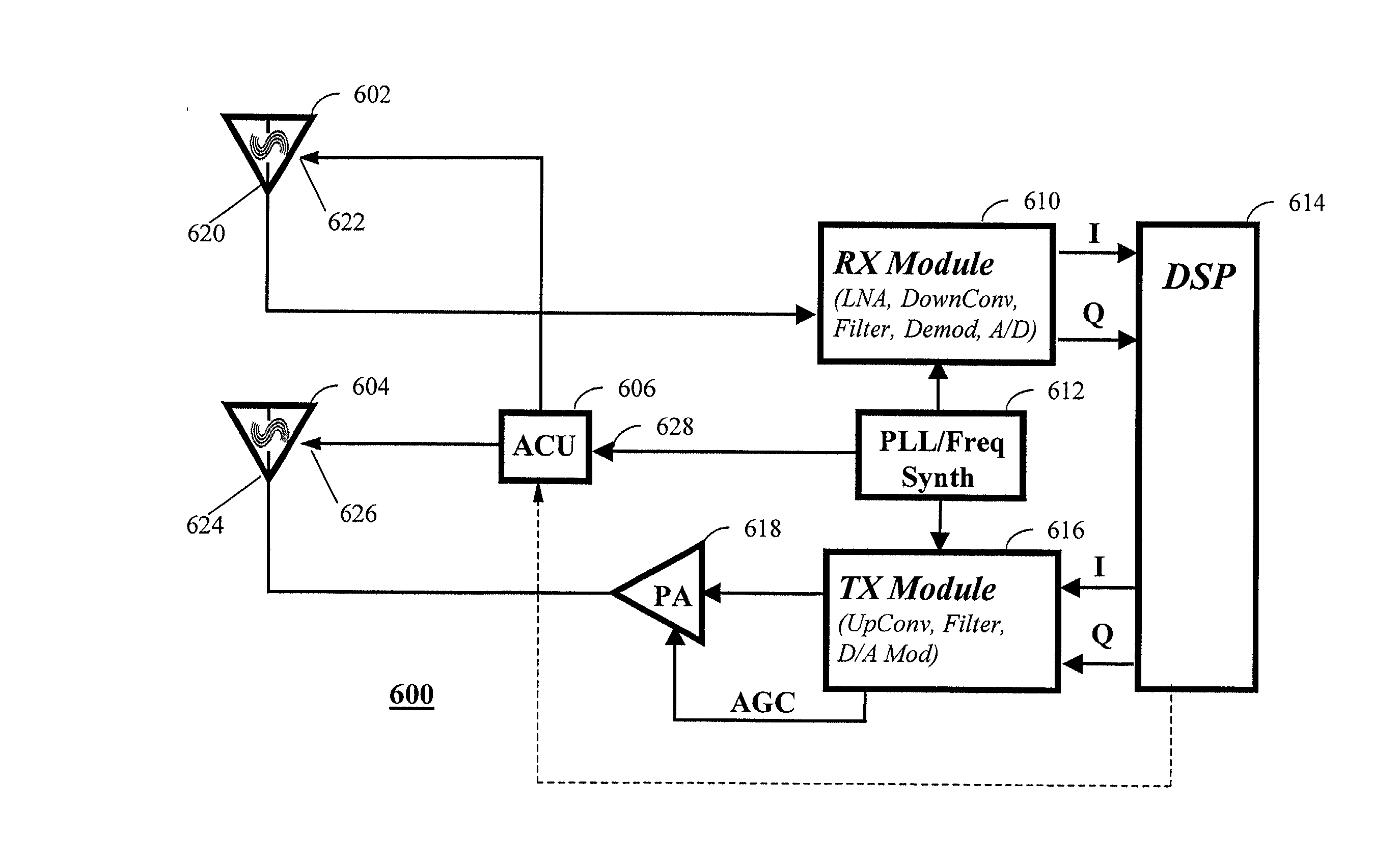
[0131] FIG. 15 is a block diagram of an alternative embodiment of a an RF system 1500 of a programmable radio. In the embodiment of FIG. 15, the RF system 1500 includes a tunable receive antenna 602, a tunable ...

first embodiment

[0137] In an integrated directional coupler and power detector, the detector output signal is sampled by an analog to digital converter which is part of the antenna control unit 606 (FIG. 19). After conversion to digital data, the ACU 606 provides data representative of the detected forward power level to the controller 614 (FIG. 6) or other circuit of the radiotelephone. In another embodiment indicated by the dashed line in FIG. 19, an analog output signal indicative of the detected power level may be provided directly to the controller 614 (FIG. 6) of the radiotelephone. In response to this control signal, the controller 614 may adapt the transmit power level, for example, to conform to an air interface specification or Federal Communications Commission standards.

[0138] FIG. 17 is a block diagram illustrating a radio communication system 1700 including a fixed or base station 1702 and a mobile or portable handset or radiotelephone 1704. In one embodiment, the radio communication s...


PUM


Abstract

The present invention relates generally to radio communication devices. More particularly, the present invention relates to a programmable radio frequency (RF) sub-system and wireless communications devices using such an integrated antenna / filter sub-system. In one embodiment, the programmable RF front end subassembly includes two antennas, RF filter sections that are integral to each antenna, and a programmable logic device as an antenna control unit. Each antenna consists of a planar inverted "F" antenna (PIFA) that is tuned to operate over a range of frequencies using voltage variable capacitors or RF switches that connect various capacitive loads in order to achieve the desired resonant frequencies. The wireless communication device further includes a control circuit coupled to the antenna to provide the control signals.

Description

[0001] The present invention relates generally to radio communication devices. More particularly, the present invention relates to a programmable radio frequency (PRF) sub-system and wireless communications devices using an integrated antenna / filter sub-system.[0002] FIG. 1 illustrates a prior art radio 100. Radio designs generally consist of three sections, as illustrated in FIG. 1. The radio 100 includes a digital or baseband section 102, a radio frequency-to-intermediate frequency (RF / IF) section 104 and a radio frequency (RF) section 106. This design is conventionally used for portable or mobile devices such as radio handsets, radiotelephones, cordless, cellular and personal communication system (PCS) phones and personal digital assistants. This design is also used for fixed radio devices such as cellular and PCS infrastructure radios.[0003] In such a radio 100, the baseband section 102 of the radio 100 includes a digital signal processor (DSP) 108 which performs functions such ...

Claims


Application Information

Patent Timeline
Patent Type & Authority Applications(United States)
IPC IPC(8): H01Q1/24H01Q9/04H04B1/04H04B1/18
CPCH01Q1/243H01Q9/0407H04B1/18H04B1/0003H04B1/0458H01Q9/0442
Inventor AUCKLAND, DAVID T.MCKINZIE, WILLIAM E. IIIMCCARTNEY, DAVID L.MENDOLIA, GREGORY S.
Owner E TENNA CORP
Why Eureka
Try Eureka