
Pressure valve

a technology of pressure regulator and retaining clamp, which is applied in the direction of machine/engine, liquid fuel feeder, fuel injecting pump, etc., can solve the problems of increasing the cost of producing the retaining clamp, the pressure regulator cannot be disposed just anywhere, and the region of the engine compartment of a motor vehicl

Inactive Publication Date: 2002-10-31
ROBERT BOSCH GMBH
View PDF8 Cites 0 Cited by
  • Summary
  • Abstract
  • Description
  • Claims
  • Application Information

AI Technical Summary

Benefits of technology

[0004] The pressure valve embodied according to the invention, having the definitive characteristics of claim 1, has the advantage over the prior art that precise positioning of the contact terminal tab is easily possible, and that the electrical contacting between the contact terminal tab and the pressure valve is assured in a simple and very safe, secure way.[0005] By means of the provisions recited in the dependent claims, advantageous refinements of and improvements to the pressure valve defined by the main claim are possible.[0006] If the gas connection is joined to the pressure valve via a joining material, and the joining material can be a meltable soldering medium, then the additional advantage is attained that in one operation, not only the connection between the gas connection and the housing part but also the connection between the contact terminal tab and the pressure valve can be made.[0007] If the gas connection is embodied in the form of a tube, and if this tube protrudes through a through hole provided in the contact terminal tab, then the advantage is attained that in a very simple way, the connection between the gas connection and the housing part and the connection between the contact terminal tab and the pressure valve can be made. If the through hole entirely surrounds the gas connection embodied in the form of a tube, then the advantage is attained that the connection can be made especially simply without major effort, and excellent tightness and good mechanical stability are attainable.[0008] The contact terminal tab secured in the region of the transition point offers the advantage that the housing part can be reinforced by the contact terminal tab in the region of the transition point, without requiring additional effort and expense to achieve this.

Problems solved by technology

In this version, it is a disadvantage that as a result of the stamping out of the tab, an opening is made in the housing, and thus the pressure regulator cannot be disposed just anywhere and in particular cannot be disposed in the region of the engine compartment of a motor vehicle.
However, this version has the disadvantage that a special retaining clamp has to be used, and the expense for producing this retaining clamp is increased.
Another disadvantage is that the electrical connection is not connected directly to the housing of the pressure regulator, which under some circumstances can cause poorer electrical contacting with the housing of the pressure valve.
However, these versions have the disadvantage that additional resilient elements are required, and that electrical transition resistances occur between the surfaces of the components used, especially a transition resistance between the housing of the pressure regulator and the resilient element where the electrical connection is connected.

Method used


Image

  • Pressure valve
  • Pressure valve
  • Pressure valve

Examples


Embodiment Construction

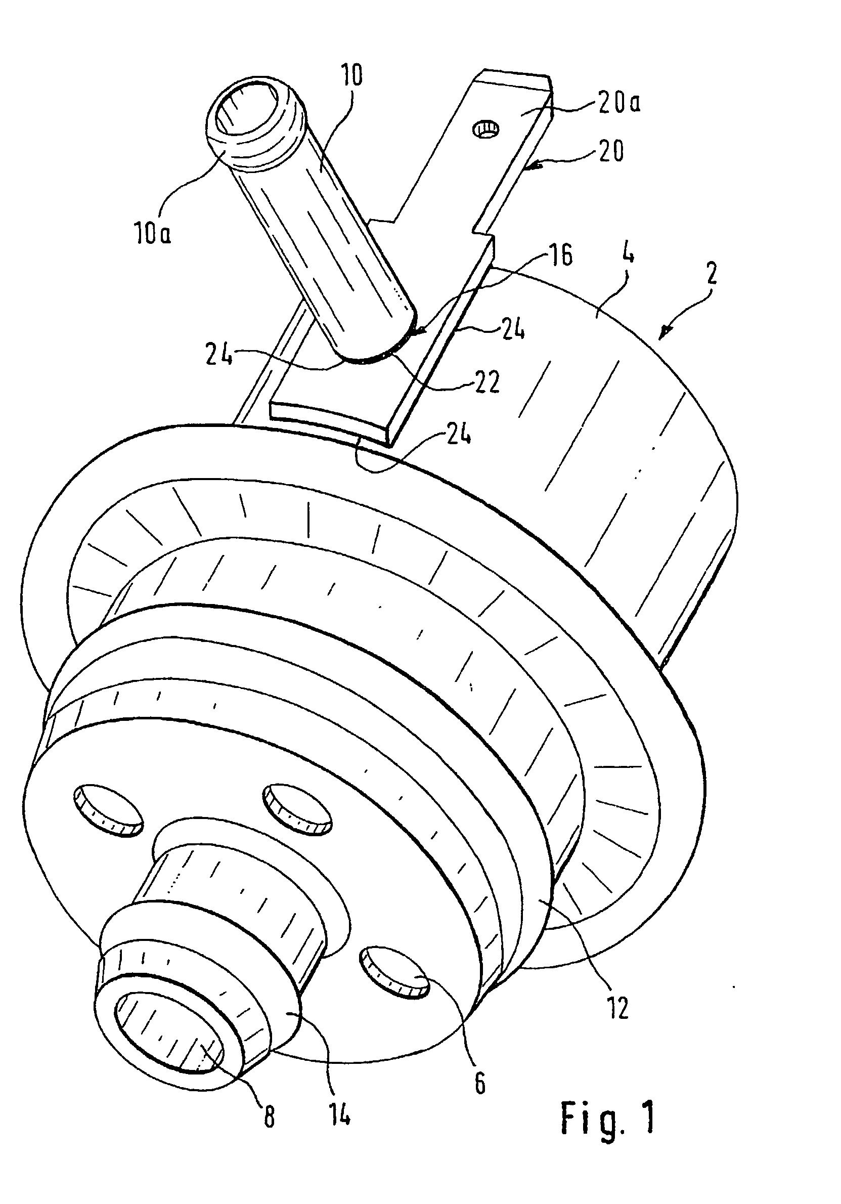
[0014] The pressure valve embodied according to the invention serves for instance to control or regulate a pressure in a fuel supply system of an internal combustion engine. As this engine, an Otto engine can for instance be considered. The fuel is for instance gasoline or diesel fuel; since gasoline is especially readily flammable, it is proposed that the pressure valve be embodied according to the invention at least whenever the fuel is gasoline.

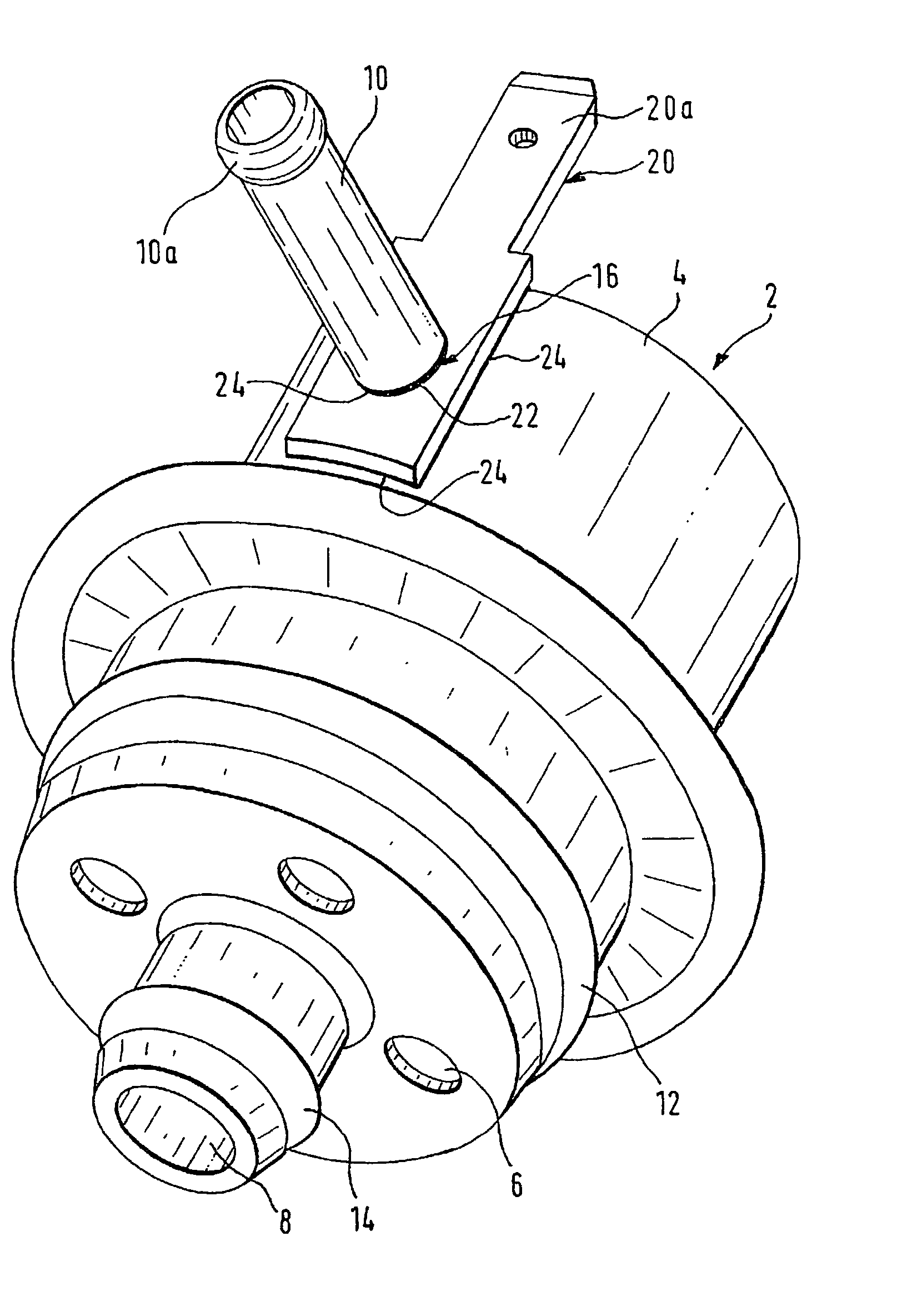
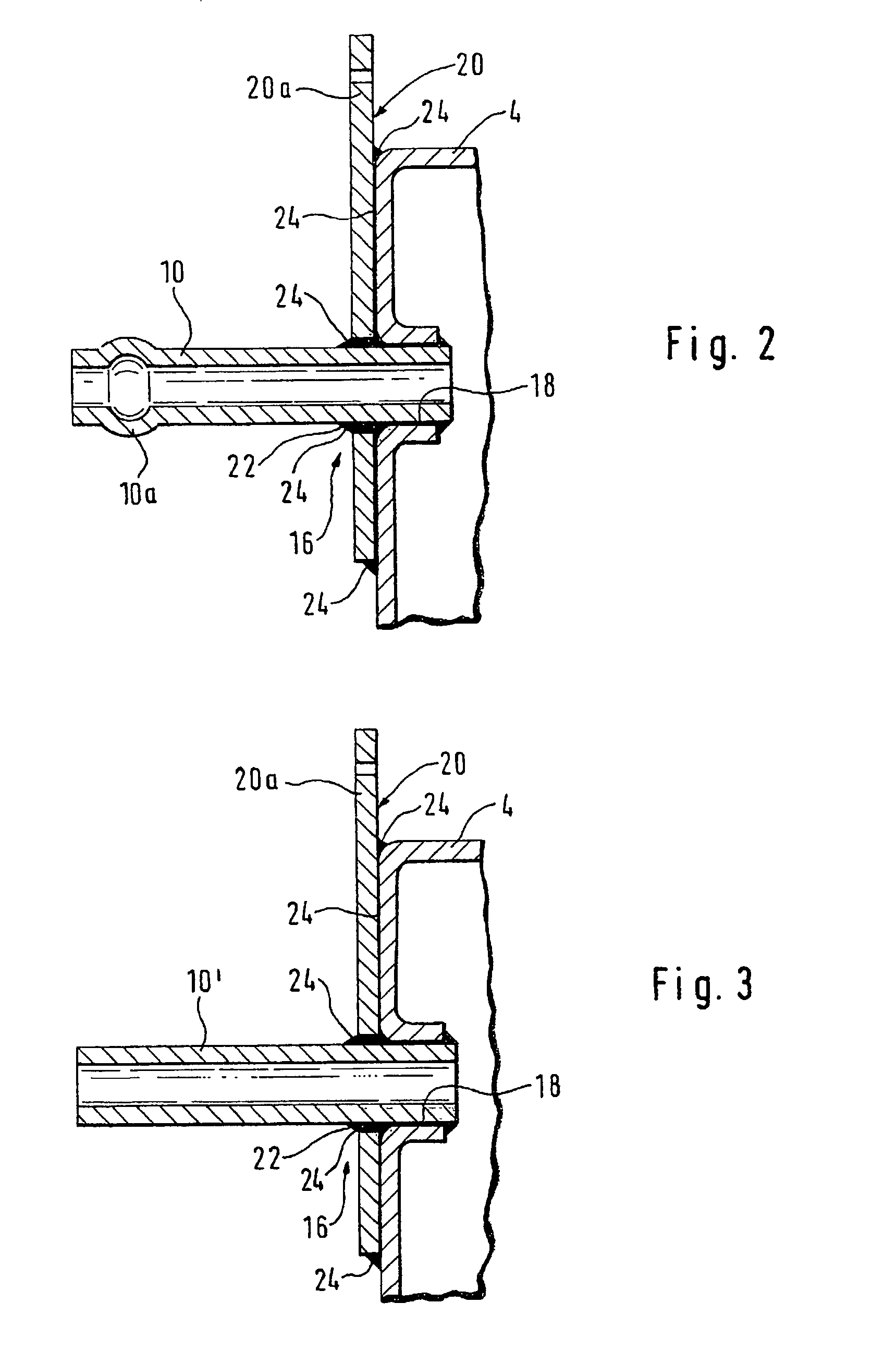
[0015] FIG. 1 shows a first, preferred, selected, and especially advantageous exemplary embodiment. FIG. 2 shows a detail of the exemplary embodiment. FIG. 2 shows a portion of a longitudinal section of the pressure valve.

[0016] In all the drawings, elements that are the same or function the same are identified by the same reference numerals. Unless otherwise noted or shown in the drawing, what is said and shown in conjunction with one of the figures applies to the other exemplary embodiments as well. Unless otherwise stated or implied by ...


PUM


Abstract

The invention relates to a pressure valve, in particular a pressure regulator, of a fuel supply system. A contact terminal tab (20) is joined solidly and permanently to a housing part (4) of a pressure valve (2) with the aid of a joining material (24). A plug prong (20a) is formed onto the contact terminal tab (20). A cable leading to an electrical ground can easily be connected to the plug prong (20a).

Description

PRIOR ART[0001] The invention is based on a pressure valve as generically defined by the preamble to claim 1.[0002] German Patent Disclosure DE 197 12 155 A1 and International Patent WO 98 / 42973, which belongs to the same patent family, show an electrically conductive component, which is retained in an electrically insulating assembly. An electrically conductive connection is connected to the electrically conductive component. Via the electrically conductive connection, the electrically conductive component is connected to the electrical potential of an electrical conductor. The aforementioned published references show various exemplary embodiments. In one of the exemplary embodiments, a plug connection is formed onto the housing of a pressure regulator. To that end, a tab is stamped from the housing and the tab is bent outward, so that the tab can be connected to a plug coupling. In this version, it is a disadvantage that as a result of the stamping out of the tab, an opening is ma...

Claims


Application Information

Patent Timeline
Patent Type & Authority Applications(United States)
IPC IPC(8): F02M69/54F02M37/00
CPCF02M69/54
Inventor TOMCZAK, STANISLAUSFRANK, KURT
Owner ROBERT BOSCH GMBH
Learn More