
Magnetic recording medium

a recording medium and magnetic technology, applied in special recording techniques, flat record carrier containers, instruments, etc., can solve problems such as disrupting recorded information, degrading read signals, and affecting the recording quality of the recording

Inactive Publication Date: 2002-09-26
TDK CORPARATION
View PDF2 Cites 45 Cited by
  • Summary
  • Abstract
  • Description
  • Claims
  • Application Information

AI Technical Summary

Benefits of technology

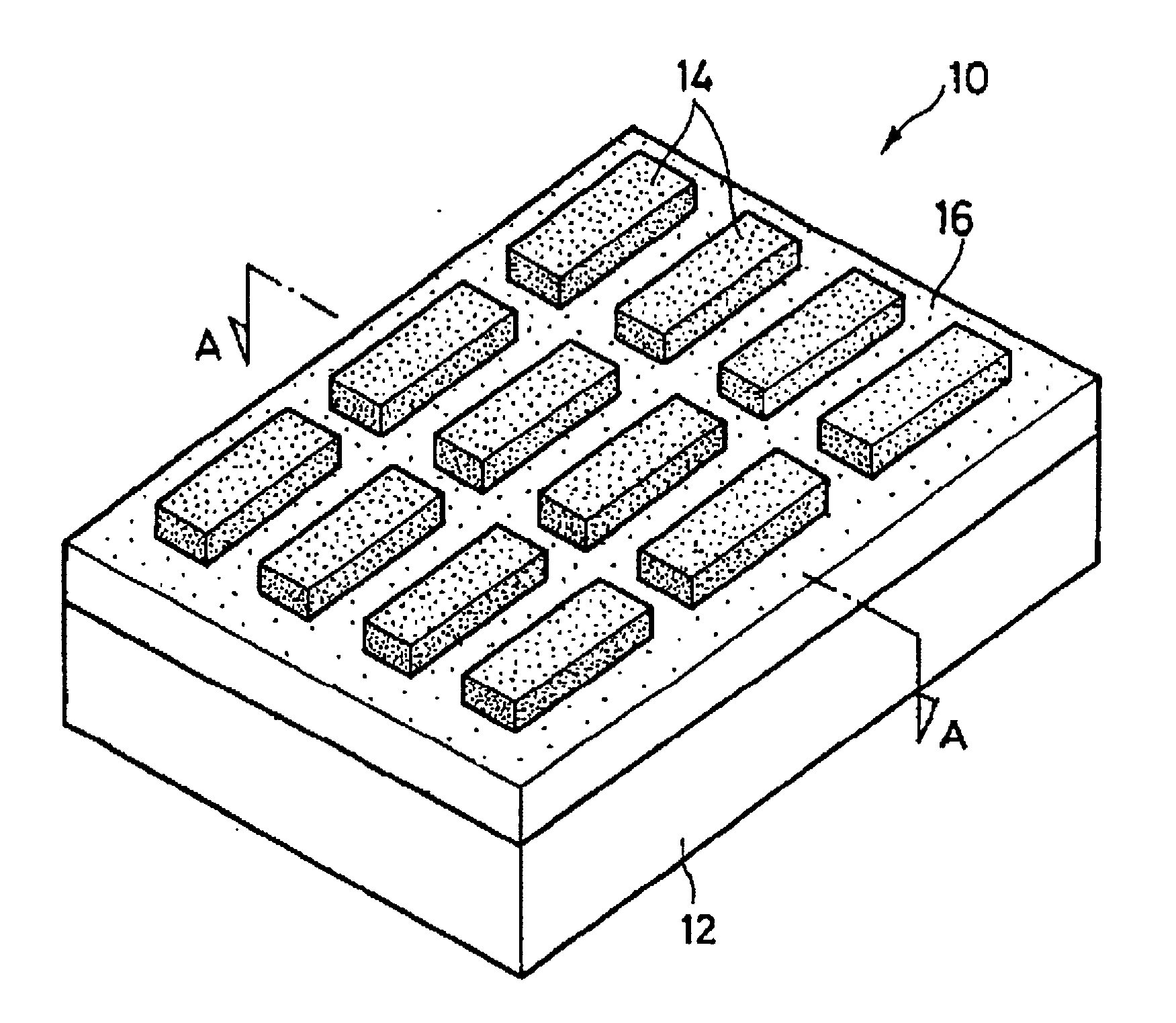
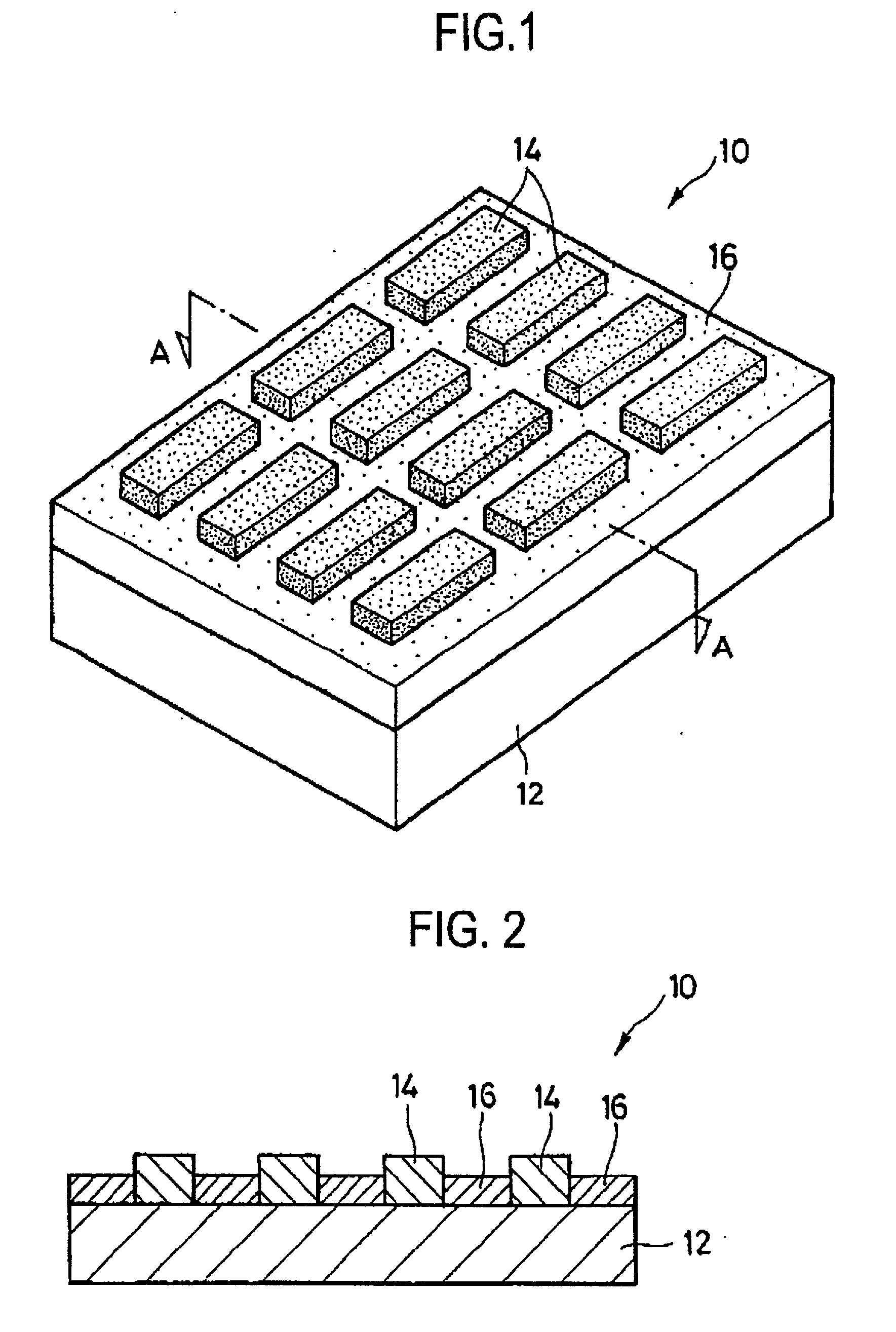
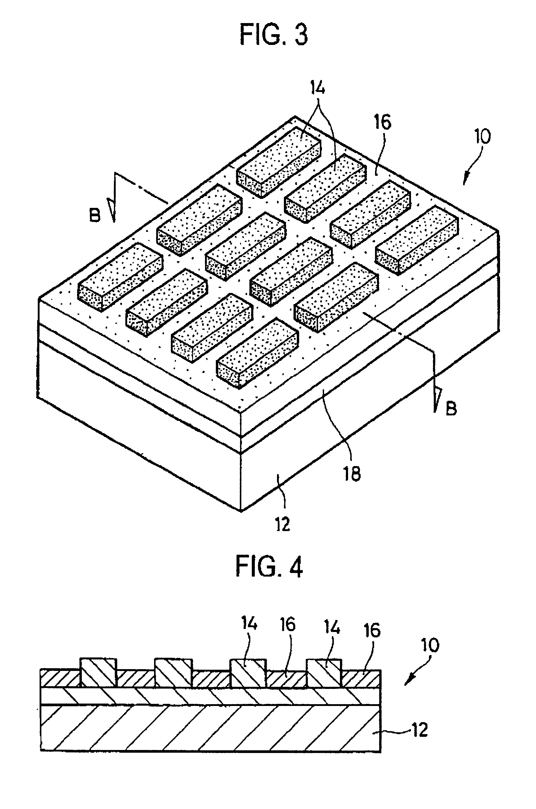
[0020] Since the surface height of the unit minute recording portions is set higher than the surface height of the non-recording portions according to the invention, the unit minute recording portions and non-recording portions form protrusions and depressions which prevent the slider from sticking to the medium. The invention eliminates a need for an extra step for providing the medium surface with depressions and protrusions.

Problems solved by technology

However, if the track width is too narrow, the interference or crosstalk between magnetic signals from adjacent recording tracks increases so that the degradation of read signals becomes a problem.
If the recording bit length is too short, the interference or partial erasure between magnetic signals from adjacent bits increases so that the degradation of read signals becomes a problem.
A magnetic disk device utilizing the contact-start-and-stop (CSS) system has the risk that the slider of the magnetic head, which is in contact with the magnetic disk at rest, can stick to the disk at start-up to disrupt the recorded information.
As discussed above, the prior art requires to employ an independent step for providing the medium surface with protrusions and depressions, resulting in a drop of productivity.
It is difficult to manufacture a medium having a large protrusion distance outside the range.

Method used


Image

  • Magnetic recording medium
  • Magnetic recording medium
  • Magnetic recording medium

Examples


Embodiment Construction

[0051] A combined magnetic head was fabricated by mounting a write head and a read head on a 30% slider which was made of AlTiC (Al.sub.2O.sub.3--TiC) to dimensions of 1.235 mm longitudinal, 1.0 mm transverse and 0.3 mm high and a weight of 1.5 mg. The write head used was an inductive head having a magnetic pole width of 0.1 .mu.m and a gap distance of 0.2 .mu.m, and the read head used was a MR head.

[0052] A magnetic disk medium was fabricated by the method shown by the flow diagram of FIG. 5. The unit minute recording portions 14 were rectangular and their dimensions were 0.2 .mu.m in the transverse direction of recording tracks, 0.1 .mu.m in the longitudinal direction of recording tracks, and 40 nm thick. The dimensions of spaces between adjacent unit minute recording portions 14, that is, the dimensions of non-recording portions 16 were 0.16 .mu.m in the transverse direction of recording tracks, 0.08 .mu.m in the longitudinal direction of recording tracks, and the non-recording p...


PUM

PropertyMeasurementUnit
surface heightaaaaaaaaaa

Abstract

In conjunction with a so-called patterned medium comprising recording tracks each having an array of unit minute recording portions of a magnetic material separated by non-recording portions of a nonmagnetic material, the invention aims to prevent a magnetic head slider from sticking to the medium. The magnetic recording medium of the invention includes recording tracks each having an array of unit minute recording portions (14) of a magnetic material separated by non-recording portions (16) of a nonmagnetic material. The surface height of the unit minute recording portions (14) is set higher than the surface height of the non-recording portions (16).

Description

[0001] 1. Technical Field[0002] This invention relates to a magnetic recording medium, more particularly, to a magnetic recording medium for use in magnetic read / write equipment such as magnetic disk equipment known as hard disk drives (HDD), and further particularly, to the structure of a magnetic recording medium having a high recording density.[0003] 2. Background Art[0004] High-capacity storage devices, especially hard disk drives featuring a high data transfer rate, quick access, high reliability and low price have marked a significant advance toward higher capacity and higher density. An improvement in areal recording density is accomplished by miniaturizing recording magnetic domains formed in the magnetic recording layer. At present, the density has exceeded 5 gigabits per square inch, with development efforts being made with the target on 10 gigabits to 100 gigabits.[0005] Used as the magnetic head for write and read operation is a combined magnetic head in which an inducti...

Claims


Application Information

Patent Timeline
Patent Type & Authority Applications(United States)
IPC IPC(8): G11B5/00G11B5/74G11B5/82G11B5/855
CPCB82Y10/00G11B5/74G11B5/743G11B5/82G11B5/855G11B2005/0002G11B2005/0005
Inventor WADA, YOSHIMITSU
Owner TDK CORPARATION
Learn More