
Flexible interconnects for fuel cell stacks

a fuel cell and flexible technology, applied in the direction of cell components, electrochemical generators, cell component details, etc., can solve the problems of low stack efficiency, high stress, difficult contact over the entire cell, etc., to facilitate electrical connection, reduce mechanical stress, and facilitate the effect of electrical connection

Inactive Publication Date: 2002-09-12
LAWRENCE LIVERMORE NAT SECURITY LLC
View PDF1 Cites 18 Cited by
  • Summary
  • Abstract
  • Description
  • Claims
  • Application Information

AI Technical Summary

Benefits of technology

[0008] A further object of the invention is to provide fuel cell interconnects that facilitates electrical connection and provides mechanical support with minimal mechanical stress.
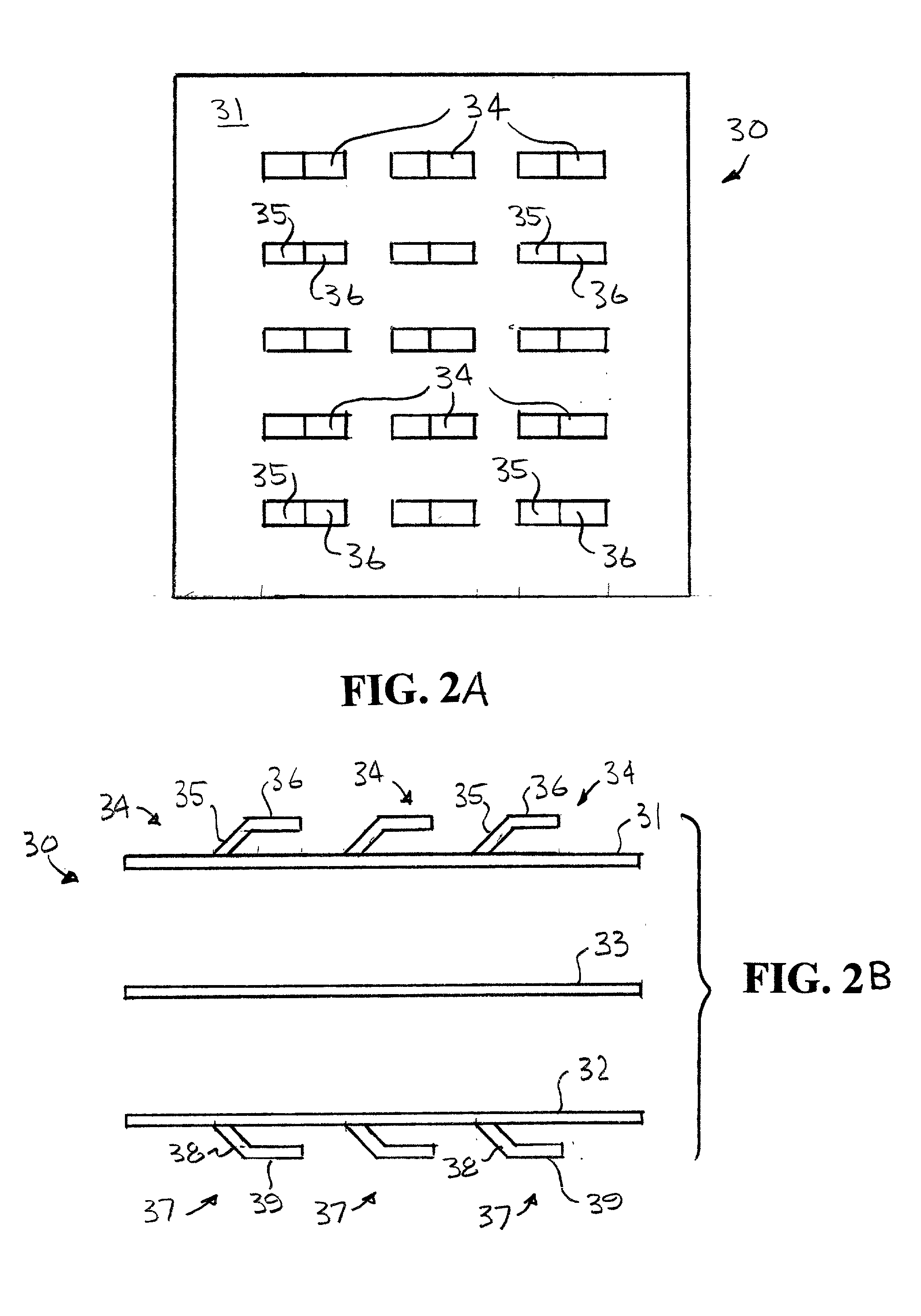
[0014] Other objects and advantages of the present invention will become apparent from the following description and the accompanying drawings. The present invention involves flexible interconnects for fuel cell stacks. The flexible member or fingers facilitates electrical connection, enables mechanical support with minimal mechanical stress, and the flexibility accommodates any imperfect flatness of the fuel cells, such as the ceramic cell. In addition, the area of the cell that is in contact with the fingers of the interconnect is smaller than the conventional rigid ribs and thus less gas starvation is provided. The interconnects can be made of three plates, for example, with a separator plate, a plate with flexible fingers or contact pads on the fuel side, and a plate with flexible fingers on the air side. Only the air side plate must be made of oxidation resistant material, while the fuel side plate can be made of flexible high conductivity material. Also, the interconnection can be fabrication in a back-to-back configuration from a single plate with flexible finger extending in opposite directions to form a common connection for two electrodes. The length and size of each flexible finger can be tailored to each individual application.

Problems solved by technology

Due to the unavoidable slight curvature of the ceramic fuel cells, good contact over the entire cell difficult.
In addition, the areas that are located below the ribs of the interconnect are not directly exposed to the gas and thus gas starvation could occur, leading to low stack efficiency.
The stacking of metal interconnects with ceramic fuel cells can also cause high stress because of the rigidity of the structure and because of the difference in thermal behavior of metals and ceramics.

Method used


Image

  • Flexible interconnects for fuel cell stacks
  • Flexible interconnects for fuel cell stacks
  • Flexible interconnects for fuel cell stacks

Examples


Embodiment Construction

[0021] The present invention involves flexible interconnects for fuel cell stacks. The interconnect of this invention facilitates electrical connection and mechanical support with minimal mechanical stress for fuel cell stacks. This leads to mechanically robust fuel cell stacks with higher stack performance at lower cost. The present invention replaces the rigid ribs of prior known interconnects with contact pads that can be in the form of flexible fingers or bridges. Due to the particular shape, and if an appropriate alloy is used, the fingers can have some flexibility which will accommodate the imperfect flatness of the ceramic fuel cells. This enables a significant improvement for the electrical contact between cells and interconnects. The mechanical stress will be smaller due to the flexibility of the fingers. In addition, the area of the single cells that is in contact with the interconnect can be large without causing any serious gas starvation because of the thinner "legs".

[0...


PUM


Abstract

An interconnect that facilitates electrical connection and mechanical support with minimal mechanical stress for fuel cell stacks. The interconnects are flexible and provide mechanically robust fuel cell stacks with higher stack performance at lower cost. The flexible interconnects replace the prior rigid rib interconnects with flexible "fingers" or contact pads which will accommodate the imperfect flatness of the ceramic fuel cells. Also, the mechanical stress of stacked fuel cells will be smaller due to the flexibility of the fingers. The interconnects can be one-sided or double-sided.

Description

RELATED APPLICATION[0001] This application relates to U.S. Provisional Application No. 60 / 274,201 filed Mar. 8, 2001, and claims priority thereof under 35 USC 120.BACKGROUND OF THE INVENTION[0003] The present invention relates to fuel cell interconnects, particularly to interconnects for fuel cell stacks, and more particular to flexible interconnects for fuel cell stacks which facilitates electrical connection and provides mechanical support with minimal mechanical stress.[0004] Fuel cells are electrochemical devices that convert the chemical energy in fuels directly into electricity. Due to the thermodynamics of the reaction of the fuel and oxygen from air, single fuel cells have a voltage of about 1 volt. Thus, for practical applications, several cells must be stacked together to generate a higher voltage. The stacking of the cells require the use of an interconnect to electrically connect the cells. Most of the time, the interconnect also serves as the gas channels for the air an...

Claims


Application Information

Patent Timeline
IPC IPC(8): H01M8/02H01M8/12H01M8/24
CPCH01M8/0228H01M8/0297H01M8/24H01M8/0247Y02E60/50
Inventor LENZ, DAVID J.CHUNG, BRANDON W.PHAM, AI QUOC
Owner LAWRENCE LIVERMORE NAT SECURITY LLC
Learn More