Ejector cycle system
- Summary
- Abstract
- Description
- Claims
- Application Information
AI Technical Summary
Benefits of technology
Problems solved by technology
Method used
Image
Examples
first embodiment
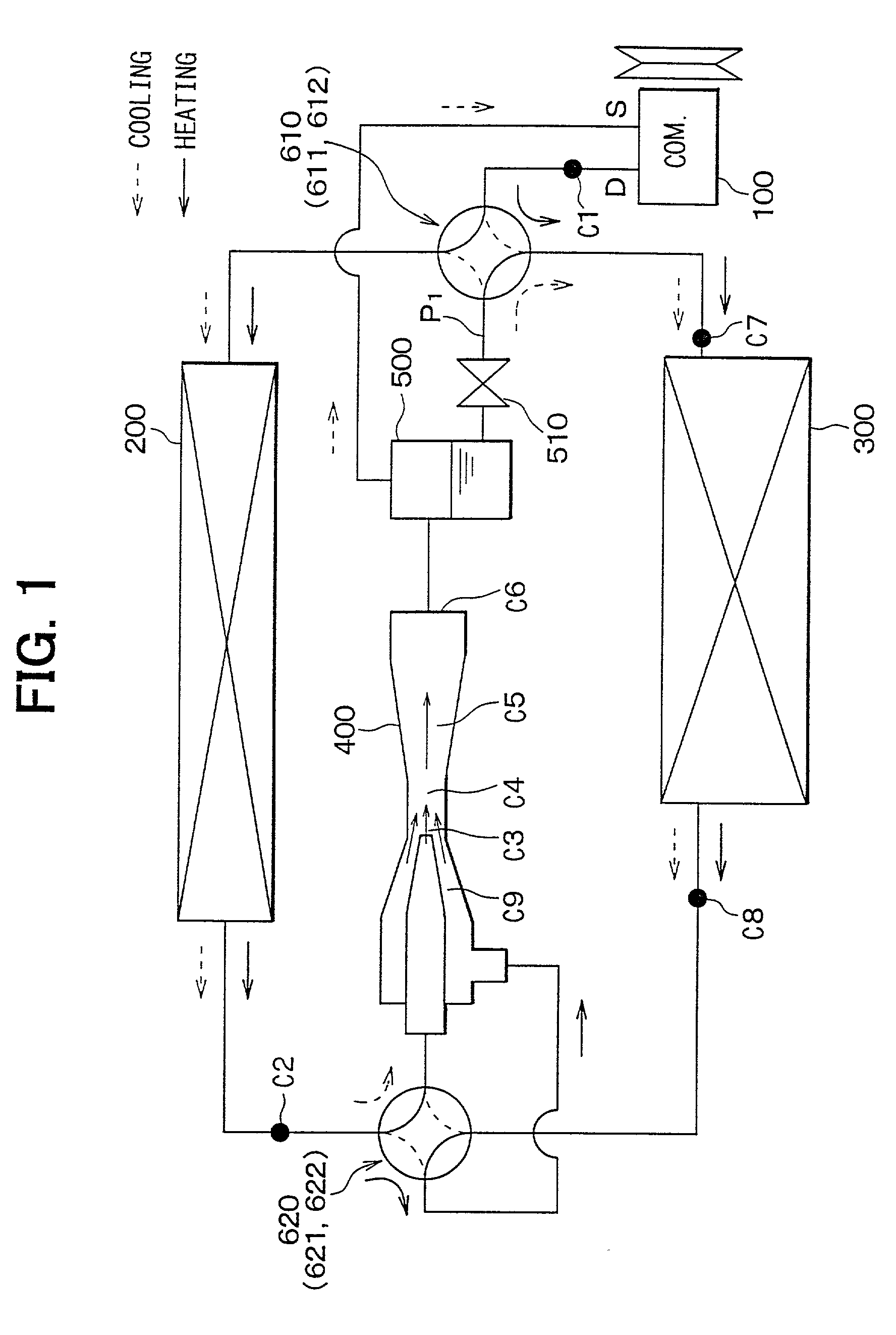
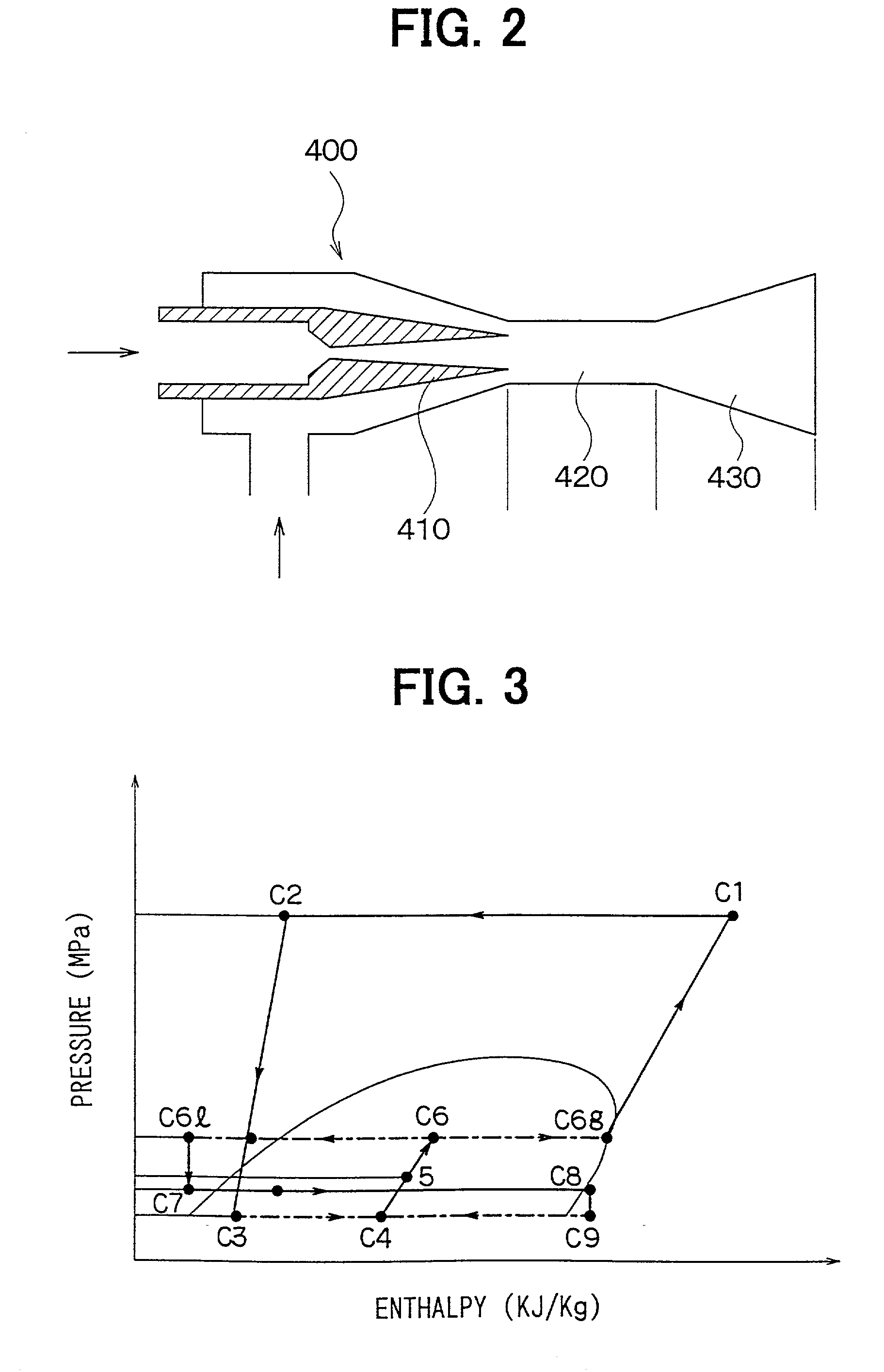
[0023] A first preferred embodiment of the present invention will be now described with reference to FIGS. 1-3. In the first embodiment, an ejector cycle system of the present invention is typically used for a vehicle air conditioner.
[0024] As shown in FIG. 1, a compressor 100 is driven by a driving source such as a vehicle engine (not shown) to suck and compress refrigerant (e.g., carbon dioxide in the first embodiment). In an exterior heat exchanger 200, refrigerant in the ejector cycle system is heat-exchanged with air (outside air) outside a passenger compartment. In an interior heat exchanger 300, refrigerant in the ejector cycle system is heat-exchanged with air to be blown into a passenger compartment. An ejector 400 decompresses and expands refrigerant at a high pressure side so that gas refrigerant evaporated at a low pressure side is sucked therein, and converts an expansion energy to a pressure energy to increase a pressure of refrigerant to be sucked into the compressor ...
second embodiment
[0043] Specifically, as shown in FIG. 4, a solenoid two-way valve 630 for opening and closing a refrigerant passage is provided at a refrigerant instruction side of the nozzle 410 of the ejector 400. Further, a decompression device (e.g., a fixed restrictor in the second embodiment) 640 is provided in a refrigerant passage through which the exterior heat exchanger 200 is connected to a refrigerant outlet side of the interior heat exchanger 300. A three-way valve 631 is provided in a refrigerant passage to switch any one of a case where refrigerant flows from the interior heat exchanger 300 into the mixing portion 420 of the ejector 400 and a case where refrigerant flows from the interior heat exchanger 300 to the fixed restrictor 640.
[0044] Next, the cooling operation and the heating operation of the ejector cycle system according to the second embodiment will be now described.
[0045] In the cooling operation, refrigerant discharged from the compressor 100 flows through the first fou...
third embodiment
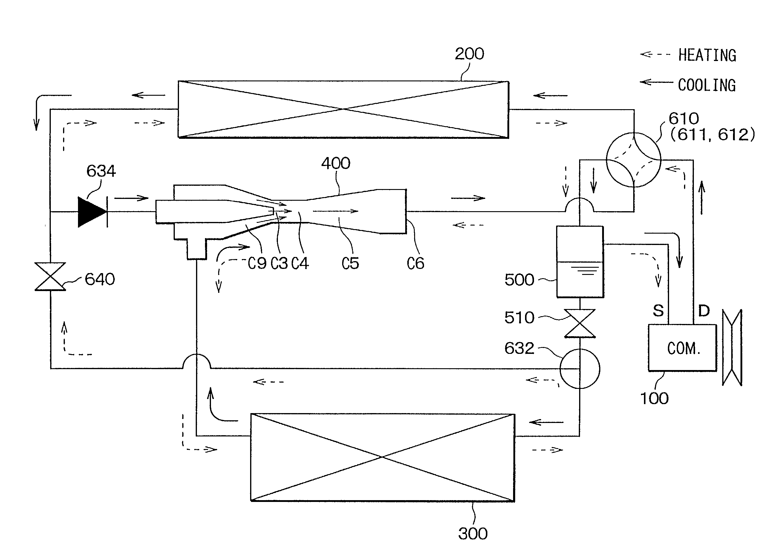
[0050] Accordingly, in the cooling operation of the ejector cycle system of the third embodiment, refrigerant discharged from the compressor 100 flows through the first four-way valve 610, the exterior heat exchanger 200, the three-way valve 633, the ejector 400, the first four-way valve 610 and the gas-liquid separator 500 in this order, and is introduced into the compressor 100. Further, liquid refrigerant from the gas-liquid separator 500 circulates the restriction device 510, the three-way valve 632, the interior heat exchanger 300, the ejector 400 (the mixing portion 420, the diffuser 430), the first four-way valve 610 and the gas-liquid separator 500 in this order.
[0051] On the other hand, in the heating operation, refrigerant from the compressor 100 circulates the first four-way valve 610, the diffuser 430, the mixing portion 420, the interior heat exchanger 300, the three-way valve 632, the fixed restrictor 640, the three-way valve 633, the exterior heat exchanger 200, the f...
PUM
 Abstract
Description
Claims
Application Information
 - R&D
- Intellectual Property
- Life Sciences
- Materials
- Tech Scout
- Unparalleled Data Quality
- Higher Quality Content
- 60% Fewer Hallucinations
Browse by: Latest US Patents, China's latest patents, Technical Efficacy Thesaurus, Application Domain, Technology Topic, Popular Technical Reports.
© 2025 PatSnap. All rights reserved.Legal|Privacy policy|Modern Slavery Act Transparency Statement|Sitemap|About US| Contact US: help@patsnap.com


