
Method and system for simulating production within a manufacturing environment

Inactive Publication Date: 2002-09-05
DELL PROD LP
View PDF7 Cites 4 Cited by
  • Summary
  • Abstract
  • Description
  • Claims
  • Application Information

AI Technical Summary

Benefits of technology

[0012] According to another aspect of the present disclosure, a method for simulating allocation of resources within a manufacturing environment is disclosed. The method includes determining available resources within selective portions of a manufacturing facility, the resources operable to be used for producing computer systems. The method further includes allocating the resources using a simulator to determine efficient utilization of the resources while minimizing impact of allocating such resources to produce the computer systems.
[0013] According to a further aspect of the present disclosure, a medium including encoded logic for simulating allocation of resources within a manufacturing environment is disclosed. The logic is operable to determine available resources within selective portions of a manufacturing facility, the resources operable to be used for producing computer systems. The logic is further operable to allocate the resources using a simulator to determine efficient utilization of the resources while minimizing impact of allocating such resources to produce the computer systems.
[0014] The present disclosure relates to a manufacturing facility that provides build-to-order products and direct shipment of products to customers. More specifically, the present disclosure relates to a manufacturing facility that is constructed and operated in such a manner as to enjoy numerous benefits, relative to prior art manufacturing facilities, including the benefit of reduced production costs. In addition, the present disclosure relates to systems and methods that may be utilized to advantage in a distribution facility, independent of the manufacturing process.

Problems solved by technology

In many markets, however, predicting customer demand is risky, at best.
For example, in the market for computer systems and related items, technological improvements are realized so frequently and component prices change so rapidly that it is difficult to accurately predict how large the market for any particular product will ultimately be.
As a result, when manufacturers in industries like information technology utilize the build-to-stock model, those manufacturers frequently find themselves with stocks of manufactured goods that are difficult or impossible to market at a profit (i.e., with stale inventory).
One of the disadvantages traditionally associated with the build-to-order model, however, is that more time is required to fill orders, in that products must be manufactured, not simply taken from stock.
Another disadvantage is that build-to-order manufacturing systems are typically less efficient than build-to-stock manufacturing systems, which drives up the cost of products that are built to order.
Simply carrying such an inventory, however, imposes costs on manufacturers, including the costs associated with warehousing the material.
Furthermore, in markets where product innovations occur rapidly, such material oftentimes become stale.
In such markets, even if using the build-to-order model, manufacturers risk significant losses when carrying significant inventories of material.
Also, it is difficult to optimize build-to-order manufacturing facilities in terms of labor requirements and space requirements, as such facilities must be able to produce of a wide variety of products.
However, additional costs are borne by a manufacture that provides a direct-ship option, in that the manufacture must provide distribution facilities, in addition to providing the manufacturing facilities.

Method used


Image

  • Method and system for simulating production within a manufacturing environment
  • Method and system for simulating production within a manufacturing environment
  • Method and system for simulating production within a manufacturing environment

Examples


Embodiment Construction

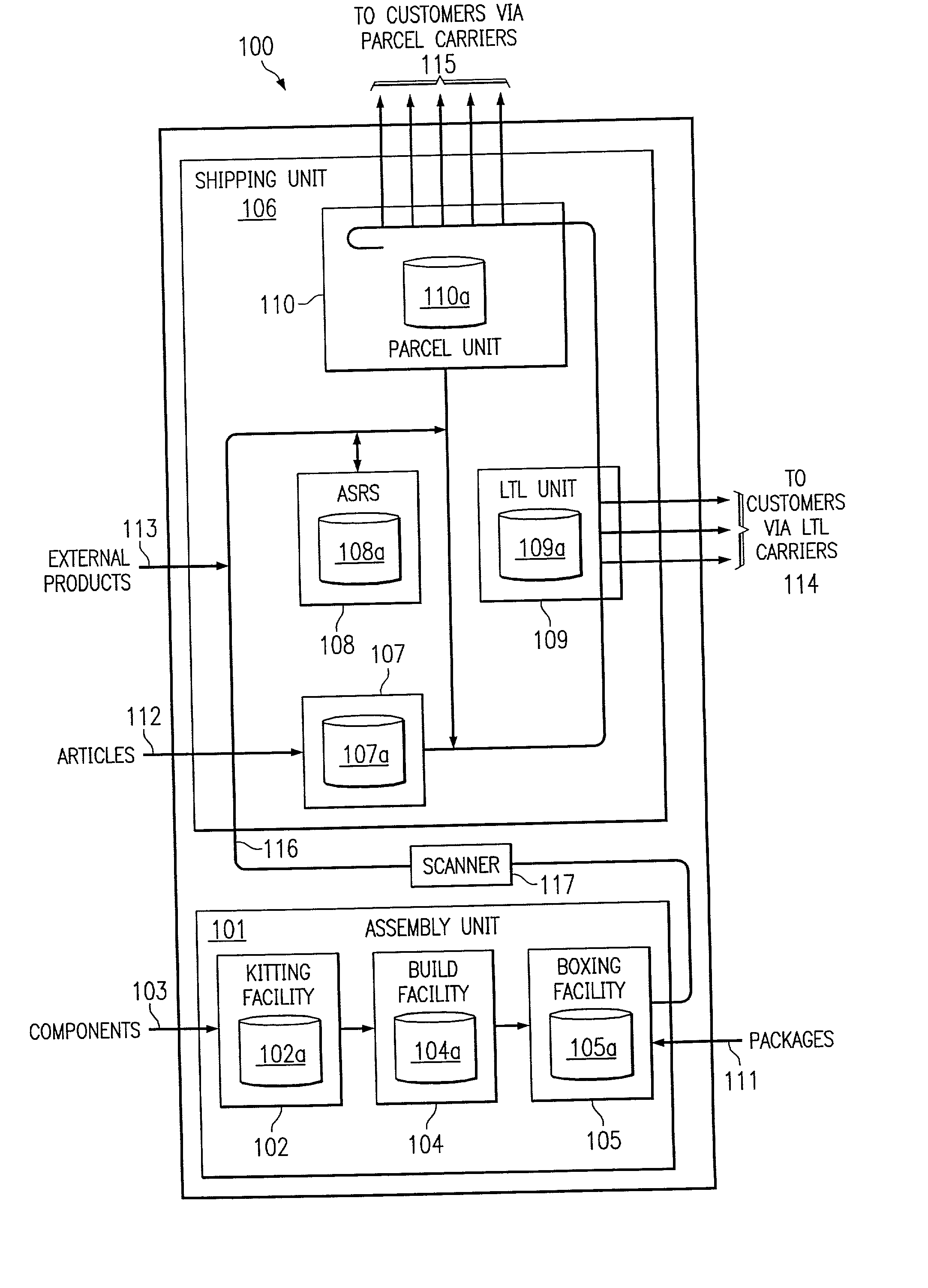
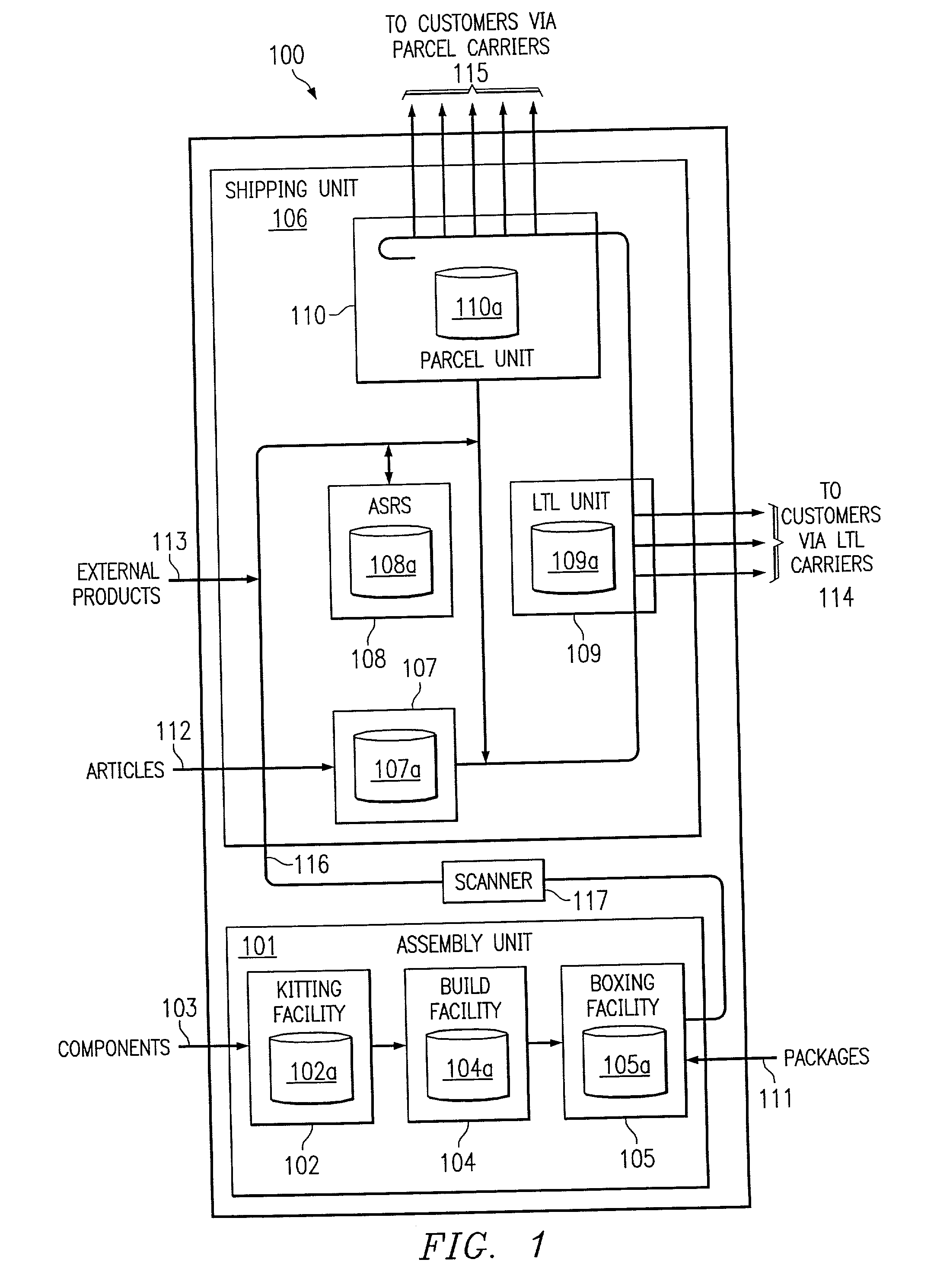
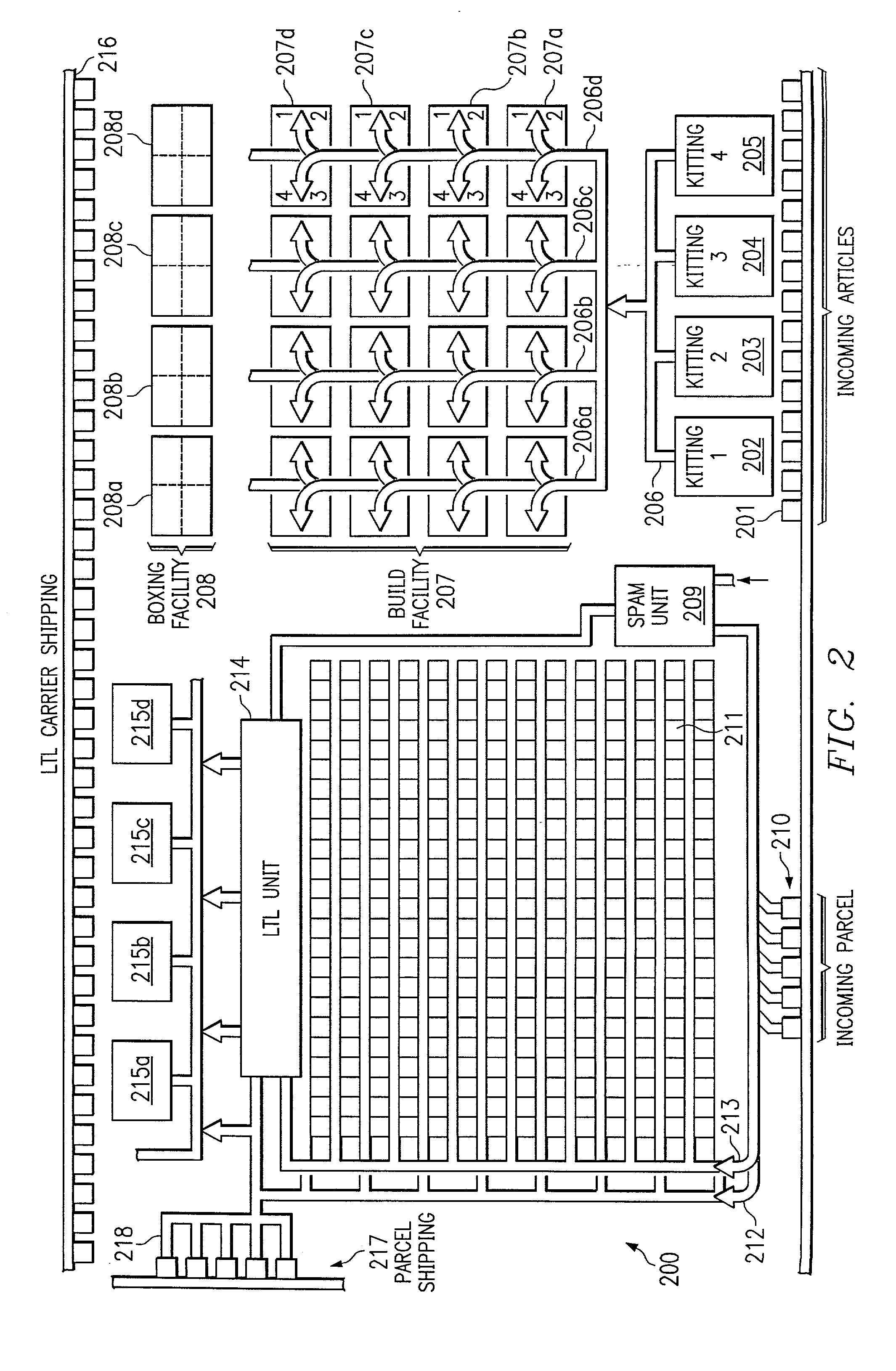
[0022] Preferred embodiments and their advantages are best understood by reference to FIGS. 1 through 6, wherein like numbers are used to indicate like and corresponding parts. Referring to FIG. 1, there is depicted an exemplary manufacturing facility 100 according to the present disclosure. In the illustrative embodiment, manufacturing facility 100 is used to manufacture computers, which are shipped directly to customers, along with associated articles (such as monitors, speakers, printers, etc). Manufacturing facility 100 is operated according to a new process and includes significant architectural enhancements, new hardware, and new control logic that provides increased quality and efficiency.

[0023] During production, the manufacturer receives one or more customer orders from a business unit and orders components from suppliers needed to manufacture the products for those orders and articles and packaging (such as boxes and protective inserts) needed to fill the orders. Preferabl...


PUM


Abstract

In accordance with teachings of the present disclosure, a method, system and logic are described for simulating production within a build to order manufacturing environment. According to one aspect, a system for allocating resources within the manufacturing environment is disclosed. The system includes a control center operably coupled to one or more databases having associated work in process profile information for selective portions of a manufacturing facility. A simulator may be communicatively coupled to the control center to simulate allocation of resources based on real-time acquisition of information associated with the WIP information.

Description

[0001] This application is related to copending Application Ser. No. 09 / ______ filed Mar. 5, 2001 entitled Method, System and Facility for Controlling Resource Allocation Within a Manufacturing Environment filed by Branden Clark Bickley et al.; and copending Application Ser. No. 09 / ______ filed Mar. 5, 2001 entitled Method, System and Facility for Monitoring Resources Within a Manufacturing Environment filed by Branden Clark Bickley.[0002] The present invention generally relates to manufacturing and, more particular to a method, system and facility for controlling resource allocation within a manufacturing environment.BACKGROUND OF THE DISCLOSURE[0003] Many years ago, manufacturers learned that, when building sufficiently large quantities of identical products, assembly lines could be used to increase the rate of production and decrease the per-unit production costs. In an assembly line, the assembly process is divided in a series of processing steps through which the work-in-proces...

Claims


Application Information

Patent Timeline
IPC IPC(8): G06Q10/06
CPCG06Q10/06
Inventor BICKLEY, BRANDEN C.GOEL, ASHISH
Owner DELL PROD LP
Learn More