
Wire-winding machine and a wire-winding method for making windings of a rotary electromechanical device

Inactive Publication Date: 2002-05-02
MITSUBISHI ELECTRIC CORP
View PDF0 Cites 10 Cited by
  • Summary
  • Abstract
  • Description
  • Claims
  • Application Information

AI Technical Summary

Benefits of technology

[0008] According to the aforementioned construction of the wire-winding machine, it is possible to prevent deformation of the coils potentially caused when winding magnet wires and achieve improved neatness of alignment of windings.
[0010] This construction serves to wind the magnet wires smoothly and efficiently.
[0012] This makes it possible to easily construct the core member positioner and provide a wire-winding machine capable of achieving improved neatness of alignment of windings.
[0014] This construction also makes it possible to easily construct the core member positioner and provide a wire-winding machine capable of achieving improved neatness of alignment of windings.
[0016] This construction makes it possible to provide a wire-winding machine capable of achieving improved neatness of alignment of windings.
[0019] This wire-winding method makes it possible to prevent deformation of the coils potentially caused when winding magnet wires and achieve improved neatness of alignment of windings.

Problems solved by technology

In a case where the magnet wires 4 are wound on the core member 3 which is arranged such that the magnetic pole teeth 3a are positioned on the outside of a bent structure with slots in the core member 3 widening outward as shown in FIG. 9, not to mention a case where the magnet wires 9 are wound on the core member 8 which is arranged such that the magnetic pole teeth 8a are positioned on the inside of a bent structure as shown in FIG. 11, however, it is difficult to make sufficient space for the wire-winding operation available.

Method used


Image

  • Wire-winding machine and a wire-winding method for making windings of a rotary electromechanical device
  • Wire-winding machine and a wire-winding method for making windings of a rotary electromechanical device
  • Wire-winding machine and a wire-winding method for making windings of a rotary electromechanical device

Examples


first embodiment

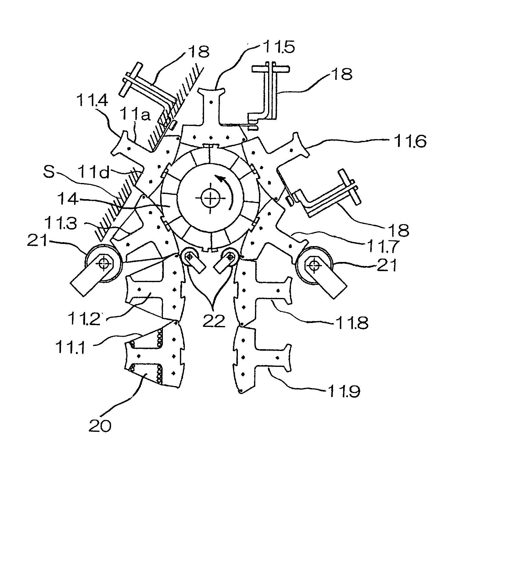
[0034] FIG. 1 is a diagram showing the construction of a wire-winding machine according to a first embodiment of the present invention and one process of wire-winding operation performed by the wire-winding machine; FIG. 2 is a diagram showing a process of the wire-winding operation performed by the wire-winding machine succeeding to the process of FIG. 1; FIG. 3 is a diagram showing a process of the wire-winding operation performed by the wire-winding machine of FIG. 1 succeeding to the process of FIG. 2; FIGS. 4A and 4B show the construction of a rotating roller 14 of the wire-winding machine of FIG. 1, of which FIG. 4A is a front view and FIG. 4B is a sectional view showing the cross section taken along lines B-B of FIG. 4A; FIGS. 5A and 5B show the construction of individual components of the rotating roller 14 of FIGS. 4A and 4B, of which FIG. 5A is a front view of a first ratchet wheel 16 and FIG. 5B is a front view of a second ratchet wheel 17; and FIG. 6 is a front view show...

second embodiment

[0043] FIGS. 7A to 7C are diagrams showing the construction of a wire-winding machine according to a second embodiment of the present invention and individual processes of wire-winding operation performed by the wire-winding machine; and FIGS. 8A to 8D are diagrams for describing the operation of a core member positioner 26 of the wire-winding machine of FIGS. 7A to 7C.

[0044] In these Figures, elements equivalent to those of the first embodiment are designated by the same reference numerals and a description of such elements is omitted. Designated by the numeral 24 are four rotatable retaining rollers serving as retaining members which are disposed with 90.degree. angular intervals in the circumferential direction. These retaining rollers 24 are disposed such that they can move outward in radial directions by a specific distance and go into contact with connecting members 12 joining and located between those core segments 11 which are positioned where coils 20 are wound.

[0045] Desig...


PUM


Abstract

A wire-winding machine for forming coils (20) on individual magnetic pole teeth (11a) of a core member (13) which is produced by joining a plurality of core segments (11), each of the core segments (11) having a yoke portion (11c) and a magnetic pole tooth (11a) projectingly formed on an inside surface (11d) of the yoke portion (11c), comprises a core member positioner including a rotating roller (14), large-diameter guide rollers (21) and small-diameter guide rollers (22) which together serve to bend the core member (13) and hold it in a position where the core segments (11.3, 11.5) adjacent to the core segment (11.4) on which the coil (20) is currently wound do not project in the direction of its magnetic pole tooth (11a) beyond a boundary surface (S) of the yoke portion (11c) of the core segment (11.4) on which the coil (20) is currently wound.

Description

BACKGROUND OF THE INVENTION AND RELATED ART STATEMENT[0001] The present invention relates to a wire-winding machine and a wire-winding method for winding wires on individual magnetic pole teeth of a core member of a rotary electromechanical device, the core member being formed by joining a plurality of core segments in beltlike form by means of connectors which serve as points of bending. More particularly, the invention is concerned with a construction for achieving improved neatness of alignment of windings.[0002] A conventional wire-winding machine 1 of this kind disclosed in Japanese Laid-open Patent Publication No. 11-98774, for instance, is constructed such that coils 5 are formed by successively winding magnet wires 4 around individual magnetic pole teeth 3a through nozzles 1a, the magnetic pole teeth 3a projecting to the outside of a core member 3 which is joined in beltlike form by connectors and wound around drums 2a of the wire-winding machine 1, as shown in FIGS. 9 and 1...

Claims


Application Information

Patent Timeline
IPC IPC(8): H02K3/18H02K3/52H02K15/095H02K1/18
CPCH02K15/095
Inventor AKITA, HIROYUKINAKAHARA, YUJIMIYAKE, NOBUAKIOMURA, KAZUYATAKAI, KEIJITOMITA, KAZUNARIKAWASUGI, NAOKI
Owner MITSUBISHI ELECTRIC CORP
Learn More