
Liquid crystal display element

a technology of liquid crystal display element and display element, which is applied in the direction of semiconductor devices, instruments, chemistry apparatus and processes, etc., can solve the problems of deteriorating contrast, reducing reflectance, and darkening image display

Inactive Publication Date: 2002-04-04
MINOLTA CO LTD
View PDF2 Cites 11 Cited by
  • Summary
  • Abstract
  • Description
  • Claims
  • Application Information

AI Technical Summary

Benefits of technology

[0012] Further, it is an object of the present invention is to provide an LCD element that has a pair of substrates and, between the substrates, a liquid crystal layer containing a liquid crystal composition that exhibits a cholesteric phase at room temperature, that is driven in response to application of a voltage to the liquid crystal layer, particularly a low voltage, and that is capable of obtaining a great light reflectance and a high contrast.
[0013] Furthermore, it is an object of the present invention to provide a multi-layer LCD element in which a plurality of liquid crystal layers are laminated and provided between a pair of substrates, that is driven with a low voltage, and that provides bright and excellent-contrast display.
[0014] According to the studies by the inventors of the present invention, in an LCD element that has, between a pair of substrates, a liquid crystal layer that contains a liquid crystal composition that exhibits a cholesteric phase at room temperature (or normal temperature) and that is driven in response to application of a voltage to the liquid crystal layer, if a mixture containing a chiral material and nematic liquid crystal is used as the liquid crystal composition, the liquid crystal layer is required to have a thickness at a certain level or more with a view to suppression of deterioration of the light reflectance and contrast in image display, as well as suppression of dielectric breakdown.
[0016] Then, the inventors of the present invention further studied the viscosity [cP (centi-poise)] and the dielectric anisotropy .DELTA..epsilon. of the liquid crystal composition, and the thickness [.mu.m] of the liquid crystal layer, and discovered that the driving with a low voltage, a great optical reflectance, and a high contrast are achieved without deteriorating the responsibility to application of a driving voltage when the viscosity of the liquid crystal composition is 30 [cP] to 150 [cP], the dielectric anisotropy .DELTA..epsilon. of the liquid crystal composition is 5 to 50, the thickness [.mu.m] of the liquid crystal layer is 3 [.mu.m] to 8 [.mu.m], and a product of these is not less than 3500.
[0027] According to the LCD element thus configured, the liquid crystal composition is a chiral nematic liquid crystal composition containing a mixture of a chiral material and a nematic liquid crystal. The viscosity a [cP] and dielectric anisotropy (.DELTA..epsilon.) b of the liquid crystal composition and the thickness c [.mu.m] of the liquid crystal layer are in ranges satisfying 30.ltoreq. a.ltoreq. 150, 5.ltoreq. b.ltoreq.50, and 3.ltoreq.c.ltoreq.8, respectively. Besides, the product of a, b, and c is not less than 3500. Therefore, the LCD element is driven with a low voltage, and is capable of obtaining a great light reflectance and a high contrast.
[0031] Furthermore, as described above, with a view to suppressing deterioration of the responsibility to application of a driving voltage when the viscosity a excessively increases, the increase of the viscosity a and the dielectric anisotropy .DELTA..epsilon. is limited. Therefore, in increasing the product of a, b, and C, the thickness C of the liquid crystal layer is dominant. Accordingly, in the case where the product of a, b, and c is more than 35000, the thickness c of the liquid crystal layer excessively increases, and it becomes difficult to lower the driving voltage as the thickness c of the liquid crystal layer increases.

Problems solved by technology

This, however, causes the light reflectance to decrease, thereby darkening image display and hence deteriorating contrast.
Therefore, when the dielectric anisotropy .DELTA..epsilon. of the liquid crystal composition is excessively increased, this causes the viscosity to increase, and an excessively increased viscosity raises problems such as deterioration of responsibility to application of a driving voltage.
In other words, when the thickness c of the above liquid crystal layer is excessively decreased, problems such as decreases in the light reflectance and the contrast and dielectric breakdown could occur.
Therefore, taking these problems into consideration, the decrease of the thickness c of the above liquid crystal layer has limitation.
Accordingly, in the case where the product of a, b, and c is more than 35000, the thickness c of the liquid crystal layer excessively increases, and it becomes difficult to lower the driving voltage as the thickness c of the liquid crystal layer increases.
In any case, it is difficult to obtain the desired chiral nematic liquid crystal that can exhibit a cholestric phase, both when the content of the chiral material is excessively less and when it is excessively much.

Method used


Image

  • Liquid crystal display element
  • Liquid crystal display element
  • Liquid crystal display element

Examples


Embodiment Construction

; and

[0048] FIG. 9 is a table showing outcomes of experiments on Comparative Examples 1 to 4.

PREFERRED EMBODIMENTS

[0049] The following description will depict an embodiment of the present invention while referring to the drawings.

[0050] An LCD element according to the present invention may be configured, for instance, as described below.

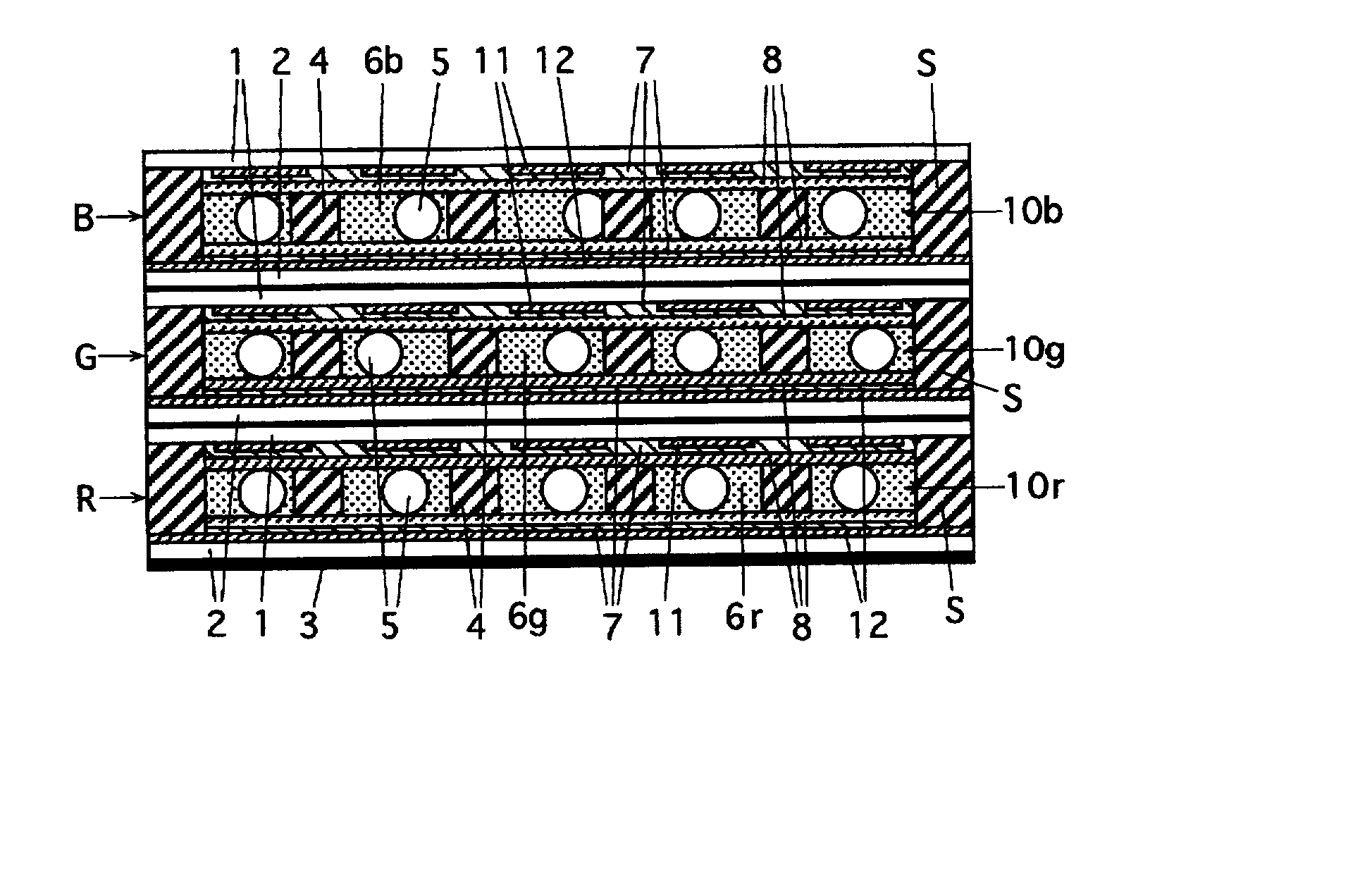
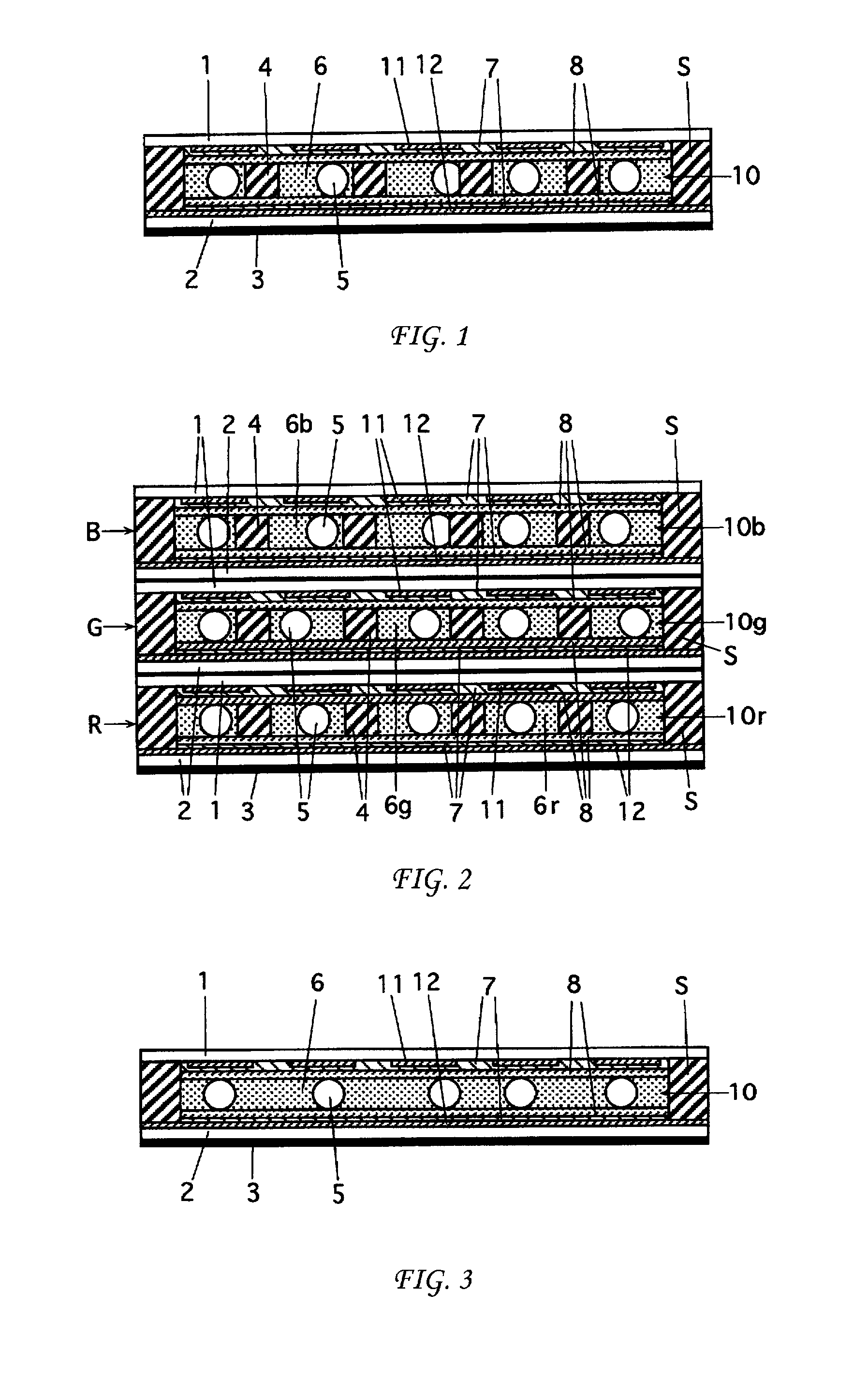
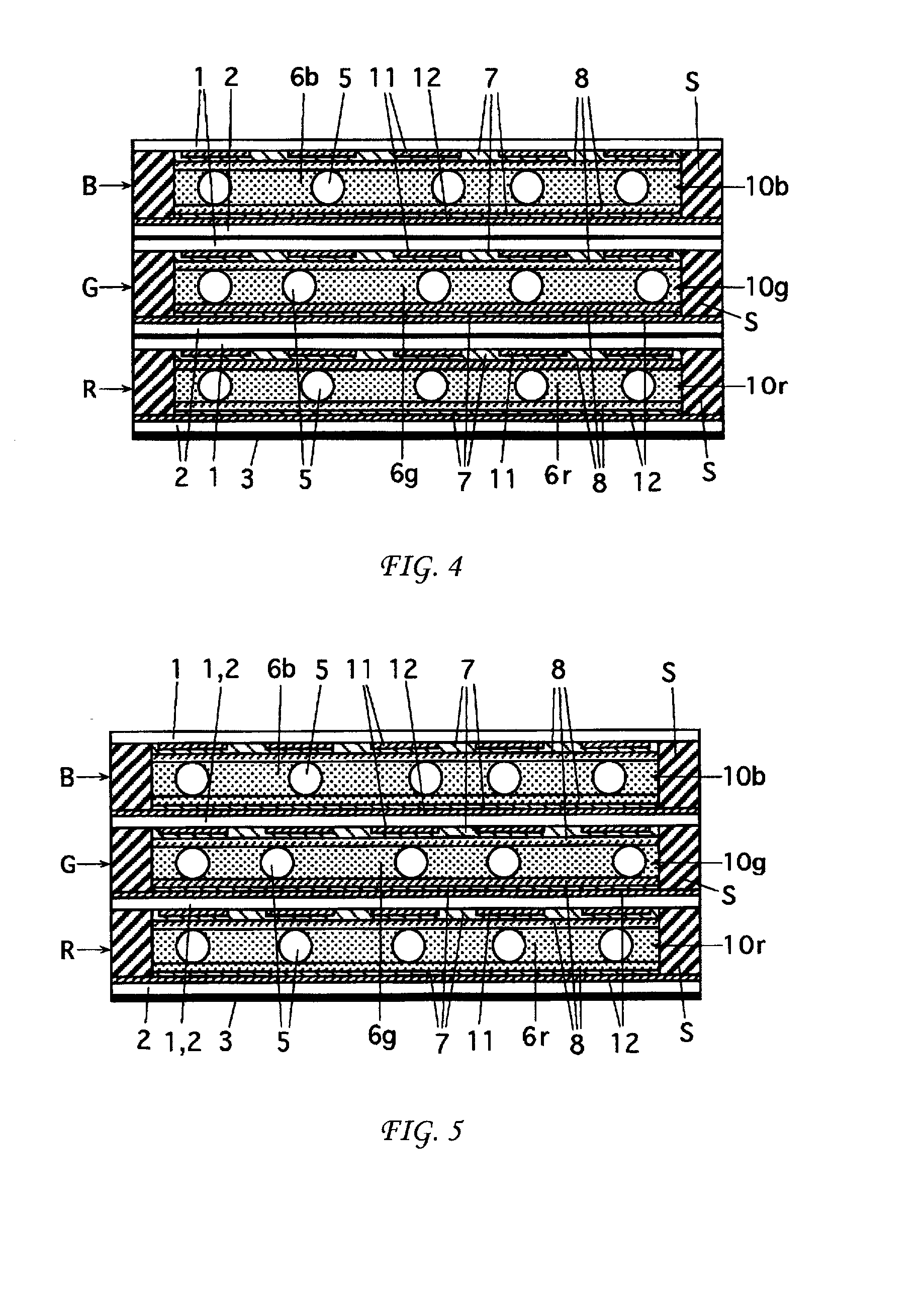
[0051] FIG. 1 is a schematic cross-sectional view of an LCD element according to the present invention. FIG. 2 shows an example of a multi-layer LCD element according to the present invention, in which three LCD elements, namely, an LCD element for blue display, an LCD element for green display, and an LCD element for red display, are laminated in the stated order. It should be noted that in the LCD elements shown in FIGS. 1 and 2, the members basically having the same configurations and functions are designated by the same referential codes.

[0052] The LCD element shown in FIG. 1 comprises a pair of substrates 1 and 2, and a liquid crystal layer 10 p...


PUM


Abstract

Disclosed is a liquid crystal display apparatus comprising a pair of substrates and a liquid crystal layer provided between the substrates, the liquid crystal layer containing a liquid crystal composition that exhibits a cholesteric phase. The liquid crystal composition contains a mixture of a chiral material and nematic liquid crystal. The liquid crystal display layer is configured to satisfies the following conditions: a viscosity a [cP] of the liquid crystal composition is in a range from 30 to 150; a dielectric anisotropy b of the liquid crystal composition is in a range from 5 to 50; a thickness c [mum] of the liquid crystal layer is in a range from 3 to 8; and a product of a, b, and c is not less than 3500.

Description

[0001] This application is based on Japanese Patent Application No. 2000-298914 filed in Japan on Sep. 29, 2000, the entire content of which is hereby incorporated by reference.[0002] 1. Field of the Invention[0003] The present invention relates to a liquid crystal display element, and particularly relates to a liquid crystal display element containing a liquid crystal component exhibiting a cholesteric phase at room temperature.[0004] 2. Description of the Related Art[0005] A liquid crystal display (LCD) element is basically composed of a pair of substrates having transparent electrodes and a liquid crystal layer provided between the substrates. The arrangement of liquid crystal molecules is controlled by application of a predetermined driving voltage to the liquid crystal layer, so that external light incident to the liquid crystal element is modulated. By so doing, intended image display, and the like, is carried out. In some cases, the LCD element may include space maintaining m...

Claims


Application Information

Patent Timeline
IPC IPC(8): C09K19/02G02F1/13G02F1/1333G02F1/1347G02F1/137G02F1/139
CPCG02F1/13718G02F1/1347
Inventor KITAHORA, TAKESHIHISAMITSU, AKIHITOUEDA, HIDEAKIMATSUMOTO, MITSUYO
Owner MINOLTA CO LTD
Learn More