
Chlorination apparatus and method

a chlorination apparatus and chlorination technology, applied in the direction of other chemical processes, liquid displacement, separation processes, etc., can solve the problems of difficult difficult to maintain consistent performance with existing erosion dissolution apparatus and methods, and difficult to achieve precise and even dissolution

Inactive Publication Date: 2002-03-14
HAMMONDS TECHN SERVICES
View PDF0 Cites 11 Cited by
  • Summary
  • Abstract
  • Description
  • Claims
  • Application Information

AI Technical Summary

Problems solved by technology

Since combinations of dry and liquid products are difficult to blend evenly prior to the pressing and forming process, the final tablet often varies in consistency and strength from batch to batch or even tablet to tablet.
Additionally, temperature, age, relative humidity and level of pressing pressure all affect the density, solubility and final chemical assay strength of each individual solid geometric tablet.
This inherent inconsistency of the dissolution characteristics of chemical tablets such as containing calcium hypochlorite makes precise and even dissolution difficult whether the dissolution process is made a "batch" at a time, or constantly as in the case of a continuous feed process.
Because chemicals such as calcium hypochlorite, which when dissolved produce chlorine in the water, are often used to achieve and maintain minute levels of residual chlorine strength with a given process, (for example, water purification), and since chlorine demands within the various processes often vary, it is extremely difficult to maintain consistent performance with existing erosion dissolution apparatus and methods.
A problem exists with the method and apparatus of dissolution of U.S. Pat. No. 5,427,748 in that because tablets are placed randomly into the feeder column of the chlorinator, the geometric shape of the chemical tablets relative to the direction of water flow as it passes up through the chlorinator produces varying degrees of dissolution.
Because the tablets are fed by gravity as the tablets within the flowing water are dissolved, the random position of the tablets within the stored column are randomly oriented in the feeder and are in a constant state of change, therefore producing inconsistent rates of erosion and dissolution as water flows over them.
Another problem with the method and apparatus of U.S. Pat. No. 5,427,748 is that with very low flow rates and erosion rates, the tablets tend to bridge.
Often, specifications call for fractional parts per million, such as 1.5 or 1.6 ppm making it more difficult to maintain desired levels when dissolution is not consistent.
Centrifugal pumps are sized to rather narrow ranges of flow performance at specific pressures, making varying their output difficult.
These changes can be complicated when a pump is utilized to inject the dissolved solution into a pressurized line.
Altering the volume of flow through a system is often difficult, since in many cases the volume available to the feeder is fixed.

Method used


Image

  • Chlorination apparatus and method
  • Chlorination apparatus and method
  • Chlorination apparatus and method

Examples


first embodiment

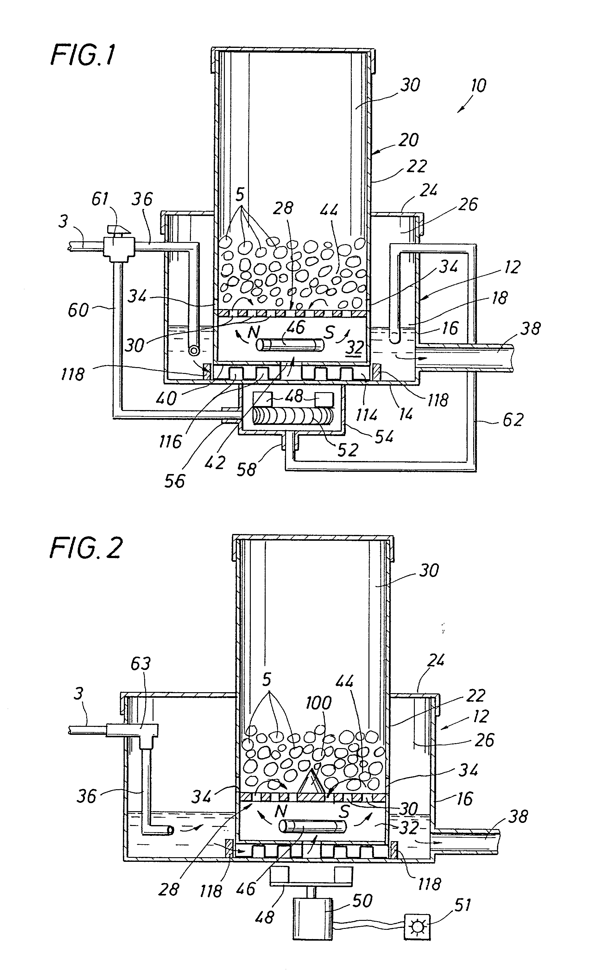
[0026] The control of the recirculation of treating solution, by means of the three way diverting valve 61, makes it possible to vary the rate of dissolution of tablets 5 within the container 20 without changing the flow rate of water passing through the apparatus 10. In other words, unlike in prior systems, the flow rate of untreated water input to the collection reservoir 26 (e.g., from inlet 3 as applied to collection reservoir 26 from the three way valve 61, line 36, and from the turbine output fluid line 62) is the same as the flow rate of treated solution water via the output line 38, and yet a variable output of chemical concentration of treated water is achieved. The arrangement and method of the invention is powered and controlled by the flow of a fixed volume of water entering into and being recirculated to various degrees, as controlled by the position of the three way diverting valve 61, through the mixing chamber 32.

second embodiment

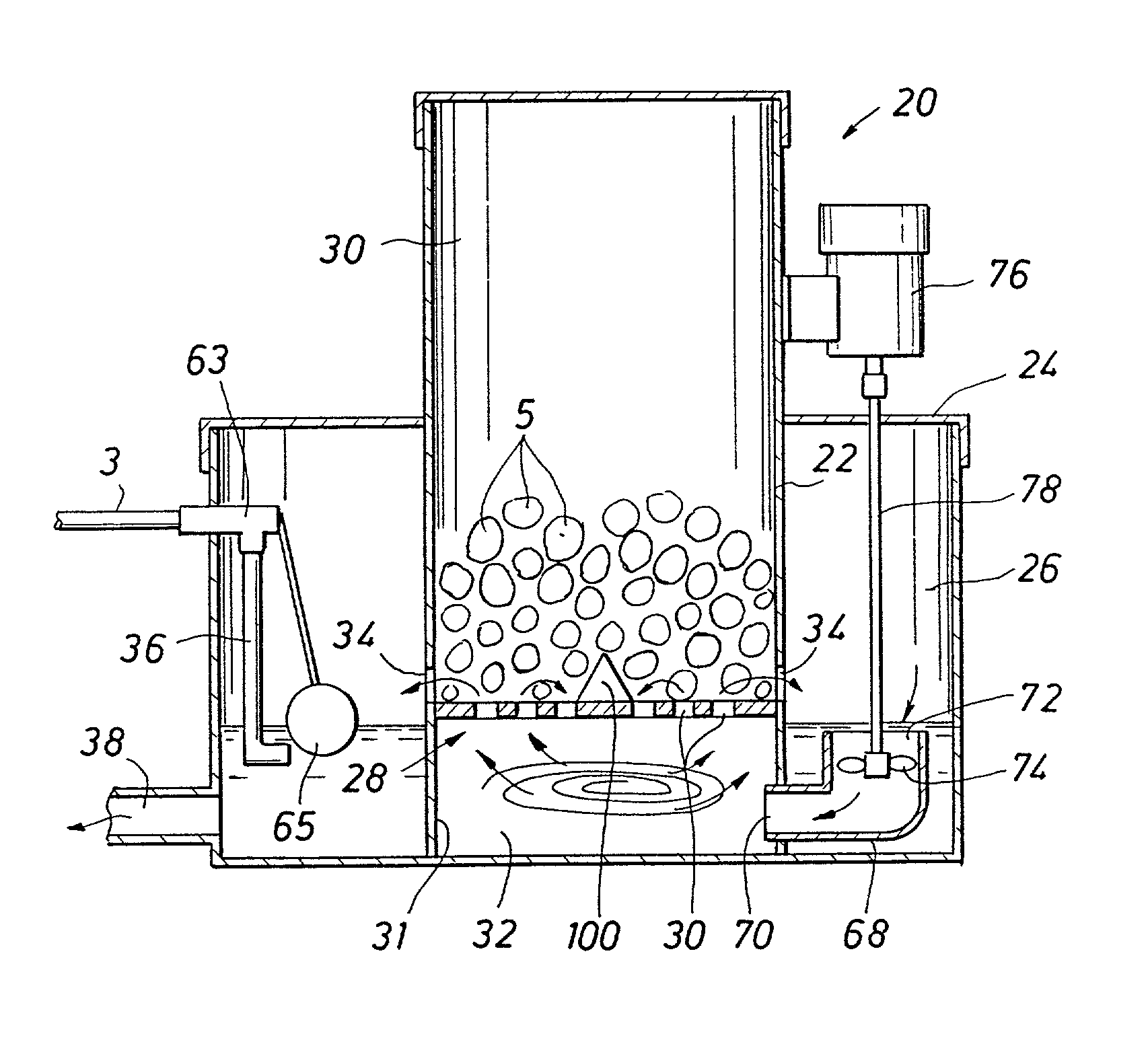
[0027] a constant flow rate, variable chemical concentration output arrangement, as illustrated in the schematic diagram of FIG. 2, provides a variable speed motor 50, manually controllable by a controller 51, to turn the driving magnetic bar 48 located outside the mining chamber 32. Again, the flow rate of liquid via the untreated liquid inlet 3 is the same as the flow rate of treated water output via outlet 31. The manually controlled variable speed motor 50, controllable by means of controller 51, controls the level of mixing, and therefore the rate of dissolution of chemical tablets in the liquid dissolving zone 44 in the upper chamber 30 and therefore the amount of dissolved chemical from tablets 5 in the constant flow rate of liquid exiting from liquid collection reservoir 26.

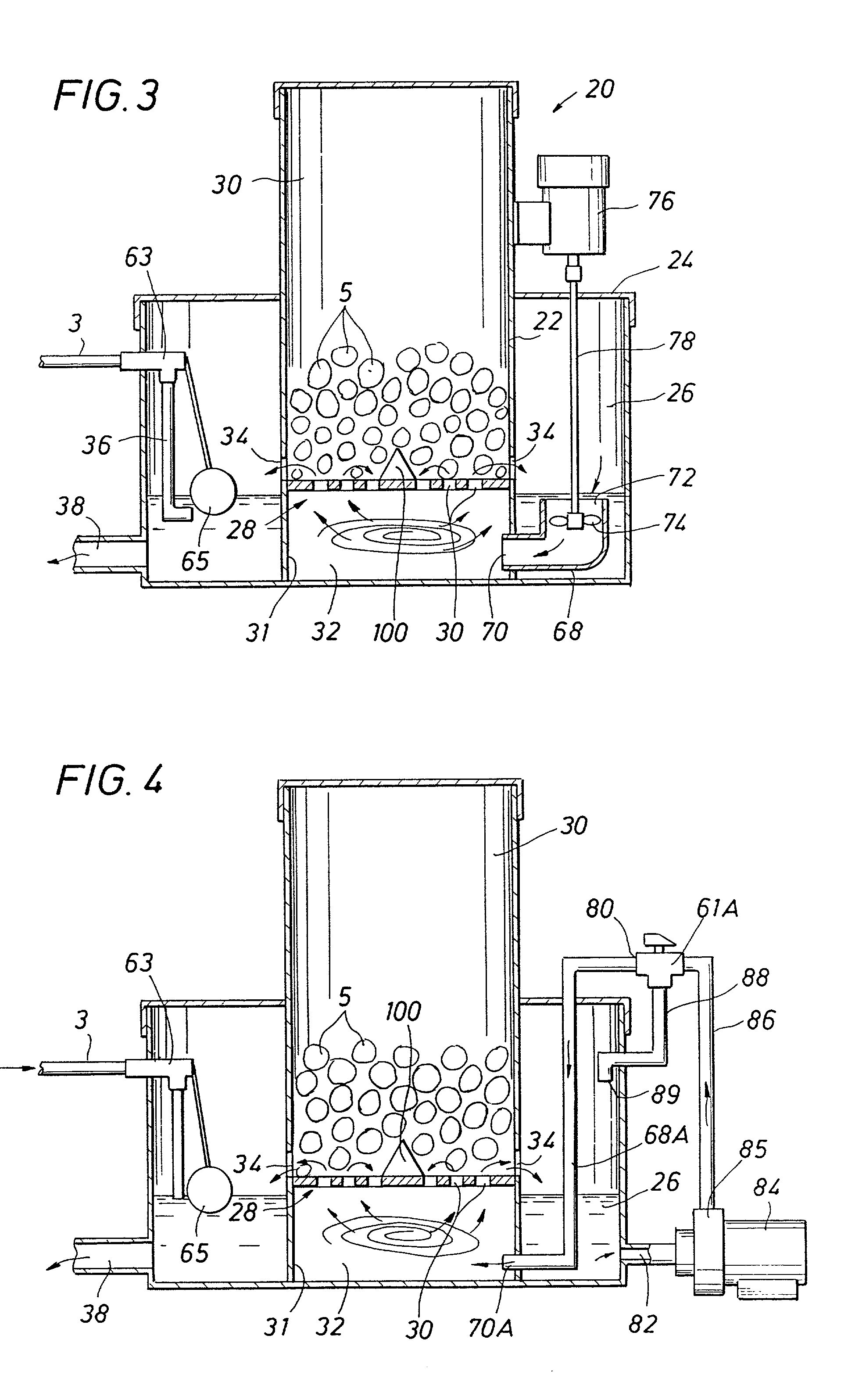
[0028] Also illustrated in FIG. 2 is a deflector 100 of a cone shape mounted on the center of grid 28, which causes tablets 5 to fall radially away from the longitudinal axis of the grid 28 in order to pr...


PUM

PropertyMeasurementUnit
rotationaaaaaaaaaa
flow rateaaaaaaaaaa
chemical dissolution rateaaaaaaaaaa

Abstract

Apparatus and method for dissolving chemical tablets for creating a variable rate of chemical dissolution in a stream of constant flow rate of untreated liquid, especially water. The apparatus includes a housing in which a container is placed. The container includes a sieve plate or perforated grid which separates the container into an upper chamber in which chemical tablets are stored and a lower mixing chamber. A collection reservoir is defined in an annular outside the container wall and inside of the housing. Several arrangements are illustrated by which a vortex of liquid is generated of controllable variable intensity in the lower or mixing chamber thereby creating uneven liquid pressure beneath the perforated grid as a function of radial distance. As a result, fluid passes aggressively through outer radial perforations or holes in the grid and which impinge on the chemical tablets stacked on the grid. The liquid circulates in the upper chamber from the outward radial position toward the center of the grid plate, while eroding the tablets, and returns to the mixing chamber. A portion of the liquid exits into the collection reservoir. Liquid communication also exits from a hole in the bottom of the lower mixing chamber, which is open to the collection reservoir. Varying the intensity of the vortex varies the rate of chemical dissolution, yet the flow rate of liquid through the apparatus is constant.

Description

[0001] This non-provisional application claims priority under 35 USC 119(e) from Provisional Application Ser. No. 60 / 143,567 filed on Jul. 13, 1999.[0002] 1. Field of the Invention[0003] This invention relates to an apparatus and method for dissolving "biscuits" or "tablets" or "pucks" containing chemicals into a liquid solution and more particularly a method of precisely controlling the dissolution rate of water purification tablets into solution. In addition, the invention provides for a system and method for either continuous or intermittent dispensing of the dissolved chemical into a flowing line, either pressurized or unpressurized, in a controlled manner for generating a specific concentration of dissolved chemical in water, and using the chemical solution to maintain an overall residual level of the dissolved chemical in the flowing line.[0004] 2. Description of Prior Art[0005] Prior arrangements used to dissolve solid chemical tablets into a liquid solution are based upon th...

Claims


Application Information

Patent Timeline
Patent Type & Authority Applications(United States)
IPC IPC(8): B01F1/00B01F5/00B01F5/04B01F5/10B01F13/08B01F15/00
CPCB01F1/00B01F1/0033B01F5/0496B01F5/10B01F13/0818B01F15/00123B01F15/00136B01F15/00155B01F15/0022B01F15/00376B01F2001/0061B01F2001/0077B01F2001/0094B01F2005/0017B01F2005/0042Y10T137/0318Y10T137/4891B01F21/4021B01F21/501B01F21/504B01F21/221B01F21/00B01F2025/91911B01F2025/913B01F25/316B01F25/50B01F33/452B01F35/2111B01F35/2112B01F35/2132B01F35/22142B01F35/21
Inventor HAMMONDS, CARL L.
Owner HAMMONDS TECHN SERVICES
Learn More