
Implant with composite coating

a composite coating and implant technology, applied in the field of in vivo implants, can solve the problems of high cost and/or technical complexity, biocompatible materials are often soft or brittle, and the best substrate materials are not the best materials to be in contact with living tissu

Inactive Publication Date: 2002-02-07
CONSENSUS ORTHOPEDICS
View PDF18 Cites 122 Cited by
  • Summary
  • Abstract
  • Description
  • Claims
  • Application Information

AI Technical Summary

Benefits of technology

[0056] An implant, representing an embodiment of the invention, can be cost effective and advantageous for at least the following reasons. The implants are simple and economical to implement. The implants have increased strength due to the structured surface being defined by a high strength material and better biocompatibility due to the use of materials for the coating that are more biocompatible than the substrate. A single implant can posses different surface areas that are individually optimized with i) some areas bearing tissue in-growth and / or on-growth composite coating, ii) some areas exhibiting the properties of the substrate material(s), and iii) some areas bearing hard surfaces formed by treatments, such as, for example, ion bombardment.[0057] All the disclosed embodiments of the invention described herein can be realized and practiced without undue experimentation. Although the best mode of carrying out the invention contemplated by the inventors is disclosed above, practice of the invention is not limited thereto. Accordingly, it will be appreciated by those skilled in the art that the invention may be practiced otherwise than as specifically described herein.[0058] For example, the individual components need not be formed in the disclosed shapes, or assembled in the disclosed configuration, but could be provided in virtually any shape, and assembled in virtually any configuration. Further, the individual components need not be fabricated from the disclosed materials, but could be fabricated from virtually any suitable materials. Further, although the implant described herein is a physically separate module, it will be manifest that the implant may be integrated into additional apparatus with which it is associated. Furthermore, all the disclosed elements and features of each disclosed embodiment can be combined with, or substituted for, the disclosed elements and features of every other disclosed embodiment except where such elements or features are mutually exclusive.[0059] It will be manifest that various additions, modifications and rearrangements of the features of the invention may be made without deviating from the spirit and scope of the underlying inventive concept. It is intended that the scope of the invention as defined by the appended claims and their equivalents cover all such additions, modifications, and rearrangements. The appended claims are not to be interpreted as including means-plus-function limitations, unless such a limitation is explicitly recited in a given claim using the phrase "means-for." Expedient embodiments of the invention are differentiated by the appended subclaims.

Problems solved by technology

A problem with this technology has been that the best substrate materials are not the best materials to be in contact with living tissue.
However, a disadvantage of this approach is that biocompatible materials are often soft or brittle.
Another disadvantage of this approach has been relatively high cost and / or technical complexity.
Heretofore, the requirements of good substrate properties, and good coating properties referred to above have not been fully met in combination.
Thus, it is rendered possible to simultaneously satisfy the above-discussed requirements of good substrate properties and good biocompatible coating properties, which, in the case of the prior art, are mutually contradicting and cannot be easily satisfied.

Method used


Image

  • Implant with composite coating
  • Implant with composite coating
  • Implant with composite coating

Examples


Embodiment Construction

[0022] The invention and the various features and advantageous details thereof are explained more fully with reference to the nonlimiting embodiments that are illustrated in the accompanying drawings and detailed in the following description. Descriptions of well known components and processing techniques are omitted so as not to unnecessarily obscure the invention in detail.

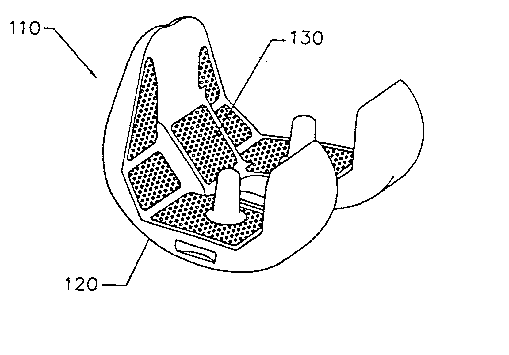
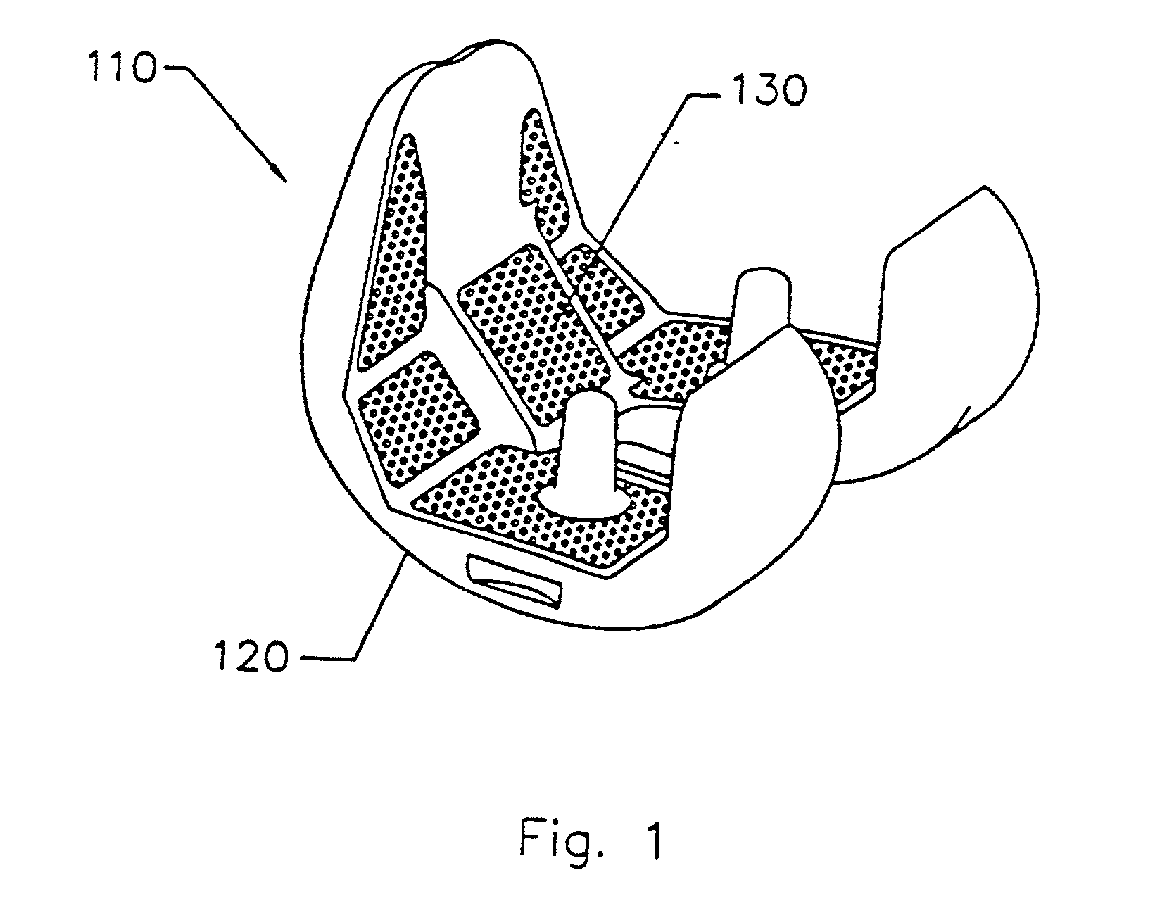
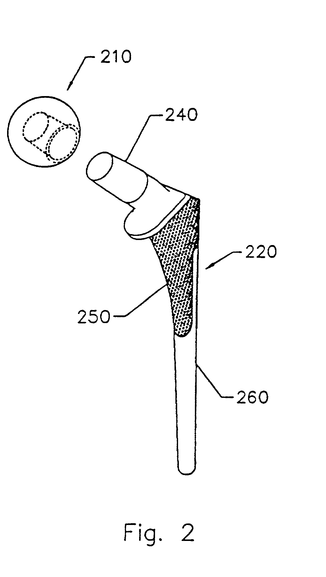
[0023] The context of the invention is providing an implant to be positioned in vivo during surgery, especially orthopedic surgery to replace a joint, such as, for example, a knee joint or a hip joint. Thus, the implant can be used in a method for orthopedic surgery that includes surgically positioning the implant within a vertebrate in need thereof. If bone growth is facilitated, the implant can be termed part of an osteoconductive process that includes contacting a bone under in vivo conditions with the implant.

[0024] Referring to the drawings, a detailed description of preferred embodiments of the invention i...


PUM

PropertyMeasurementUnit
thicknessaaaaaaaaaa
thicknessaaaaaaaaaa
depthaaaaaaaaaa

Abstract

Systems and methods are described for implants with composite coatings to promote tissue in-growth and / or on-growth. An implant includes: a substrate; a structured surface formed on at least a portion of the substrate; and a biocompatible coating deposited on at least a fraction of the structured surface. The systems and methods provide advantages in that the implant has good biocompatibility while the biocompatible coating has good strength.

Description

[0001] 1. Field of the Invention[0002] The invention relates generally to the field of in vivo implants. More particularly, preferred embodiments of the invention are directed to an orthopedic prosthesis having a composite coating to promote tissue in-growth and / or tissue on-growth.[0003] 2. Discussion of the Related Art[0004] Prior art implants are known to those skilled in the art. For example, conventional implants are typically composed of stainless steel, cobalt-chrome, or titanium alloy.[0005] A problem with this technology has been that the best substrate materials are not the best materials to be in contact with living tissue. Therefore, what is required is a solution that can provide a biocompatible coating on a substrate.[0006] One approach in an attempt to solve the above-discussed problems involves simply coating an implant substrate with a biocompatible material. However, a disadvantage of this approach is that biocompatible materials are often soft or brittle.[0007] An...

Claims


Application Information

Patent Timeline
Patent Type & Authority Applications(United States)
IPC IPC(8): A61F2/00A61F2/30A61F2/36A61F2/38A61L27/30
CPCA61F2/30767A61F2/3094A61F2/30965A61F2/36A61F2/3662A61F2/367A61F2/3859A61F2002/30016A61F2002/30906A61F2002/30925A61F2002/30929A61F2002/30968A61F2002/3097A61F2002/3098A61F2002/30981A61F2002/3611A61F2002/3625A61F2002/3631A61F2002/365A61F2250/0019A61F2310/00017A61F2310/00023A61F2310/00029A61F2310/00131A61F2310/00179A61F2310/00407A61F2310/00485A61F2310/00491A61F2310/00538A61F2310/00544A61F2310/00574A61F2310/0058A61F2310/00796A61F2310/00976A61L27/306A61P19/00
Inventor DESPRES, ALFRED S. IIIELWOOD, EUGENE J.AHARONOV, ROBERT R.EHLERS, PETERANDERSEN, KNUT
Owner CONSENSUS ORTHOPEDICS
Learn More