Threaded compression-enhanced fastening device for use with threaded rods
- Summary
- Abstract
- Description
- Claims
- Application Information
AI Technical Summary
Benefits of technology
Problems solved by technology
Method used
Image
Examples
embodiment 10
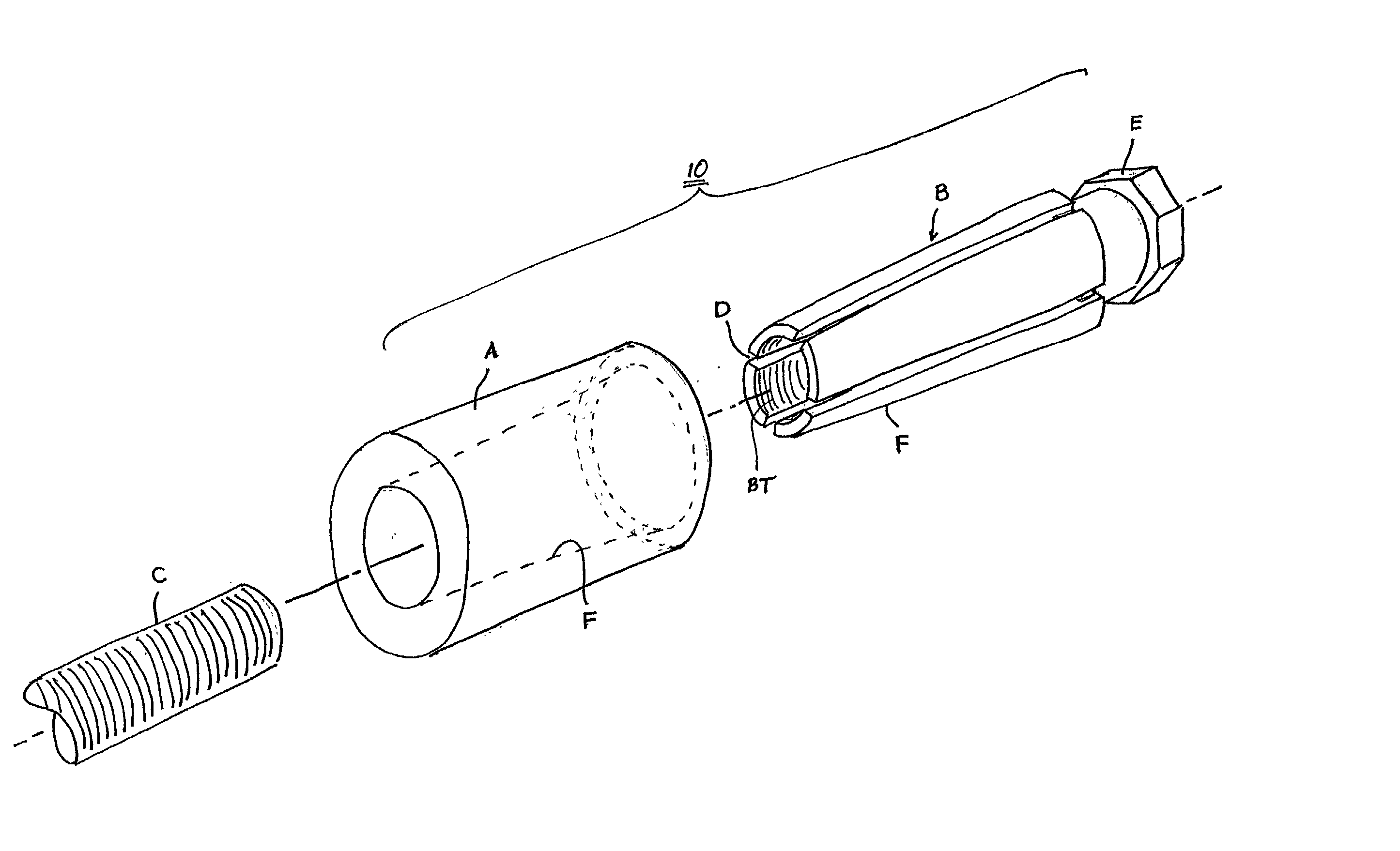
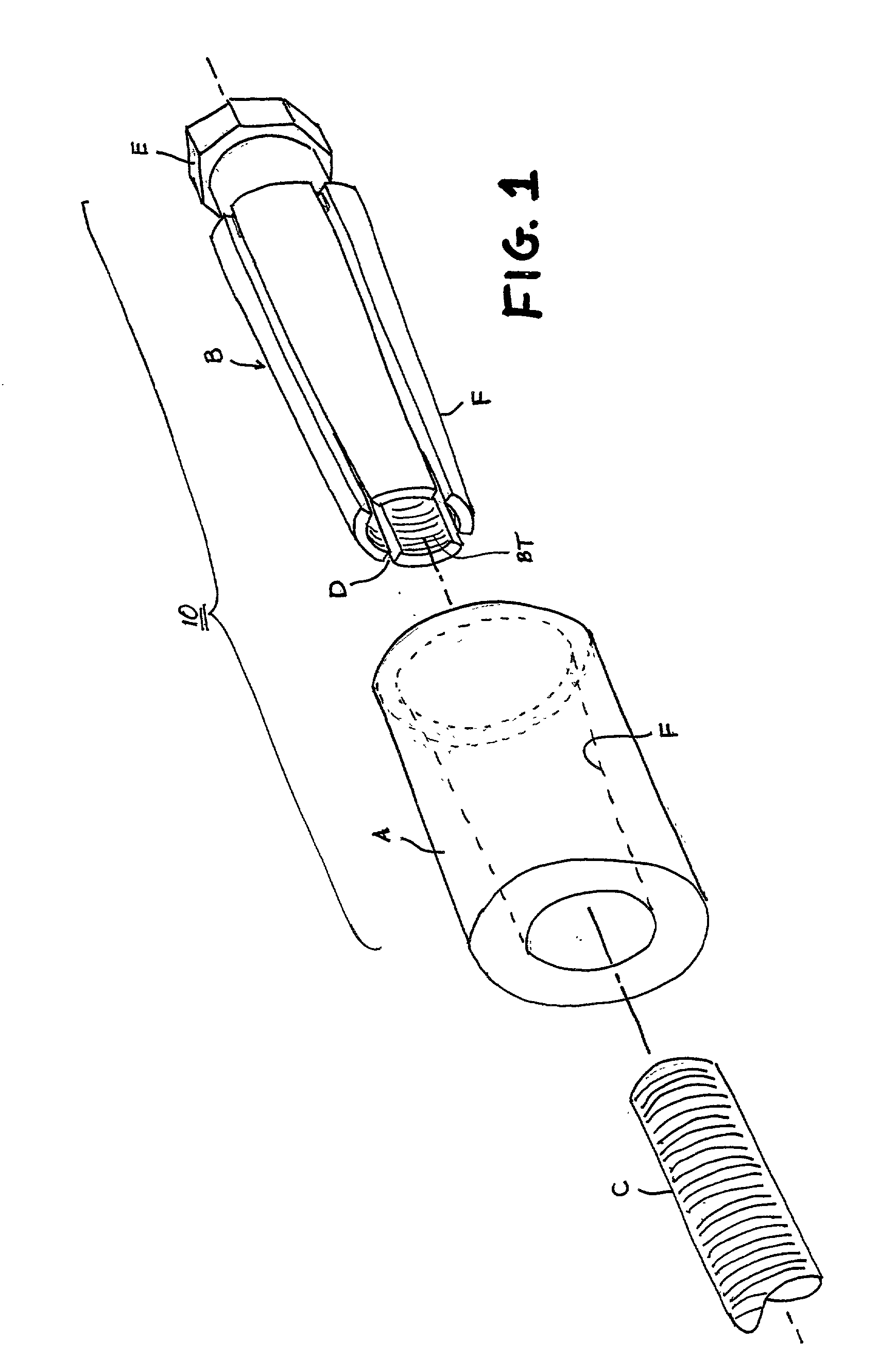
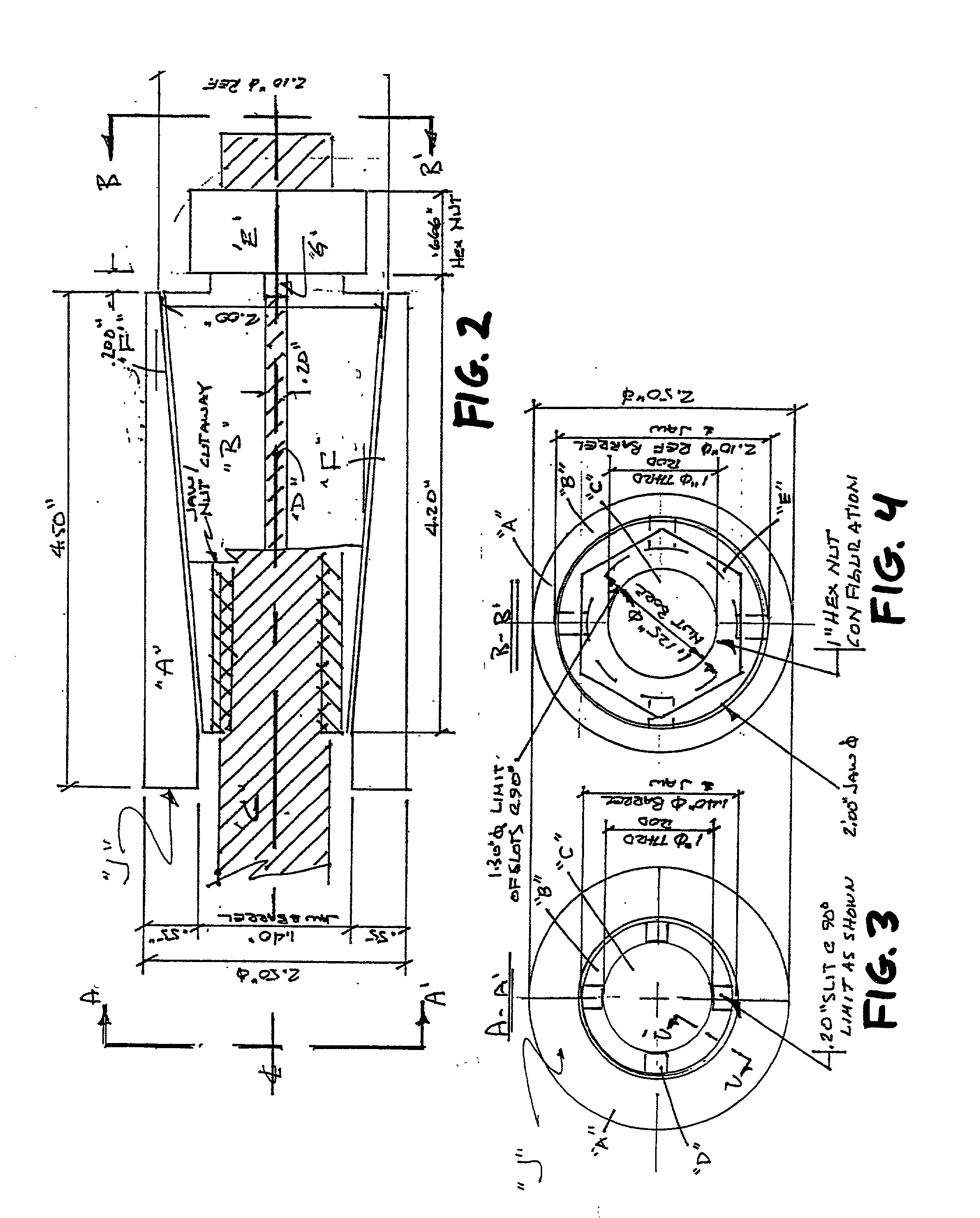
[0027] FIGS. 1 and 2 are an exploded perspective view and a cutaway sectional view, respectively, of a first preferred embodiment 10 of the present invention that engages a threaded rod "C", i.e. a threaded FRP rod. In this embodiment, the rod's externally threaded portion and the device's internally threaded portion are shown to have complimentary diameters of 1". It can be readily understood, however, that other diameters may be used. In fact, the thread diameter and other dimensional data that is noted here and in the drawings is only provided in order to give some perspective to the presentation. The specified dimensions should not be regarded as providing any sort of limitation on the design or function of the device, or as a limitation on the scope of the below-stated claims.
[0028] As suggested by FIG. 1, the device 10 is passed over and threaded onto the rod "C". Not shown, but evident from FIG. 2, is the component to which the device is being fastened. This component would b...
first embodiment
[0030] The barrel "A" and jaw section "B" are independent of each other while having complementary configurations. The barrel "A" has a smooth tapered bore. The jaw section "B" includes slots "D" that define individual jaws. The jaws section "B" further has internal jaw threads "BT" that threadably engage the threaded rod "C" and a smooth external surface that slidingly engages the smooth tapered bore of the barrel In this first embodiment, the jaw section "B" includes an integral nut "E". The device 10 may be installed through the following procedure and removed by reversing the procedure. The barrel "A" and jaw section "B" are so formed that when the barrel "A" is placed over the rod "C", the integral nut "E" of the jaw section "B" may be easily threaded unto the rod "C" with the internal threads "BT" of the jaw section "B" turning loosely about the threaded rod "C" as the jaw section "B" turns into the barrel "A". The integral nut "E" of the jaw section and its internal threads "...
second preferred embodiment
[0036] FIGS. 6, 7 and 8 relate to a device 10 made according to a second preferred embodiment. As best shown in FIG. 6, the second preferred device 10 has an alternative jaw configuration where the rotating portion of the device "E2" is independent of the jaw section "B2". In more detail, the device 10 uses a jaw section "B2" having only two slots "D2" (equally positioned at 180 degrees) , and the rotating portion of the device 10 comprises a separable nut section "E2" or cap. It should be noted that while this embodiment shows a hexagonal "nut" configuration, any configuration that permits application of sufficient torque may be used.
[0037] FIGS. 7 and 8, taken together with FIG. 6, show how the separable nut section "E2" selectively engages the jaw section "B2" through a cooperative "bayonet" -like arrangements of lips and slots.
[0038] FIG. 7 shows the nut section "E2" as viewed from the downstream side that engages the jaw section "B2". Clearly visible are a pair of inwardly exte...
PUM
 Abstract
Description
Claims
Application Information
 - R&D
- Intellectual Property
- Life Sciences
- Materials
- Tech Scout
- Unparalleled Data Quality
- Higher Quality Content
- 60% Fewer Hallucinations
Browse by: Latest US Patents, China's latest patents, Technical Efficacy Thesaurus, Application Domain, Technology Topic, Popular Technical Reports.
© 2025 PatSnap. All rights reserved.Legal|Privacy policy|Modern Slavery Act Transparency Statement|Sitemap|About US| Contact US: help@patsnap.com


