
Electro-optical component having a reconfigurable phase state

a technology of electronic components and phase states, applied in the field of electronic components having reconfigurables, can solve the problems of widening the gap between the speed of the microprocessor affecting the conversion procedure of optical-electrical-optical (oeo) and the volume of network traffi

Inactive Publication Date: 2001-12-13
INTELLIGENT PIXELS
View PDF0 Cites 110 Cited by
  • Summary
  • Abstract
  • Description
  • Claims
  • Application Information

AI Technical Summary

Benefits of technology

[0017] It is a further object of the present invention to provide such a switch in which the circuit computes a reconfigurable phase pattern or hologram to optimize the performance of the switch by reducing optical losses, and to minimize the quanta of optical signal falling into adjacent channels, i.e. crosstalk.

Problems solved by technology

There is an inherent problem with the hybrid approach when used in a networked environment.
Historically, microprocessor speed has doubled almost every 18 months, but demand for network capacity has increased at a much faster rate, thus causing a widening gap between the microprocessor speed and the volume of network traffic.
The effect of this gap places a great burden on the electronic cross connections for optical links that are implemented in metropolitan and long-haul networks.
The procedure of optical-electrical-optical (OEO) conversion becomes more difficult as the speed of the link reaches OC-48 (2.5 Gbps), and is even more difficult at higher speeds.
At such speeds, the electronic circuitry of the OEO causes a network bottleneck.
However, despite a significant investment for development of an all photonics OXC, it is presently a major challenge to design a reliable all photonics, non-blocking, low loss, scalable and reconfigurable optical switch, even for N in the order of 32-40.
Several different technologies have been tried for optical interconnects, but none is yet regarded as a technology or market place leader.
This is due, in part, to an impracticality of the switching media or to a lack of scalability in cross-connecting a suitable number of input and output ports.
A limitation of these switch mechanisms is scalability.
It is difficult to construct guided wave switches greater than an 8.times.8 size because they use substrates of limited size.
The interconnection of several small switches to construct a large switch is also impractical because of the bulkiness of optical fiber harnesses.
Disadvantages of a MEMS-based switch include limitations relating to mechanical, thermal and electrostatic stability.
Another disadvantage of the MEMS-based switch is its optics, which typically require highly collimated optical paths, usually employing microlenses that cannot significantly diffract the light beam.
A disadvantage of such materials is the cost and difficulty of large-scale manufacturing.

Method used


Image

  • Electro-optical component having a reconfigurable phase state
  • Electro-optical component having a reconfigurable phase state
  • Electro-optical component having a reconfigurable phase state

Examples


Embodiment Construction

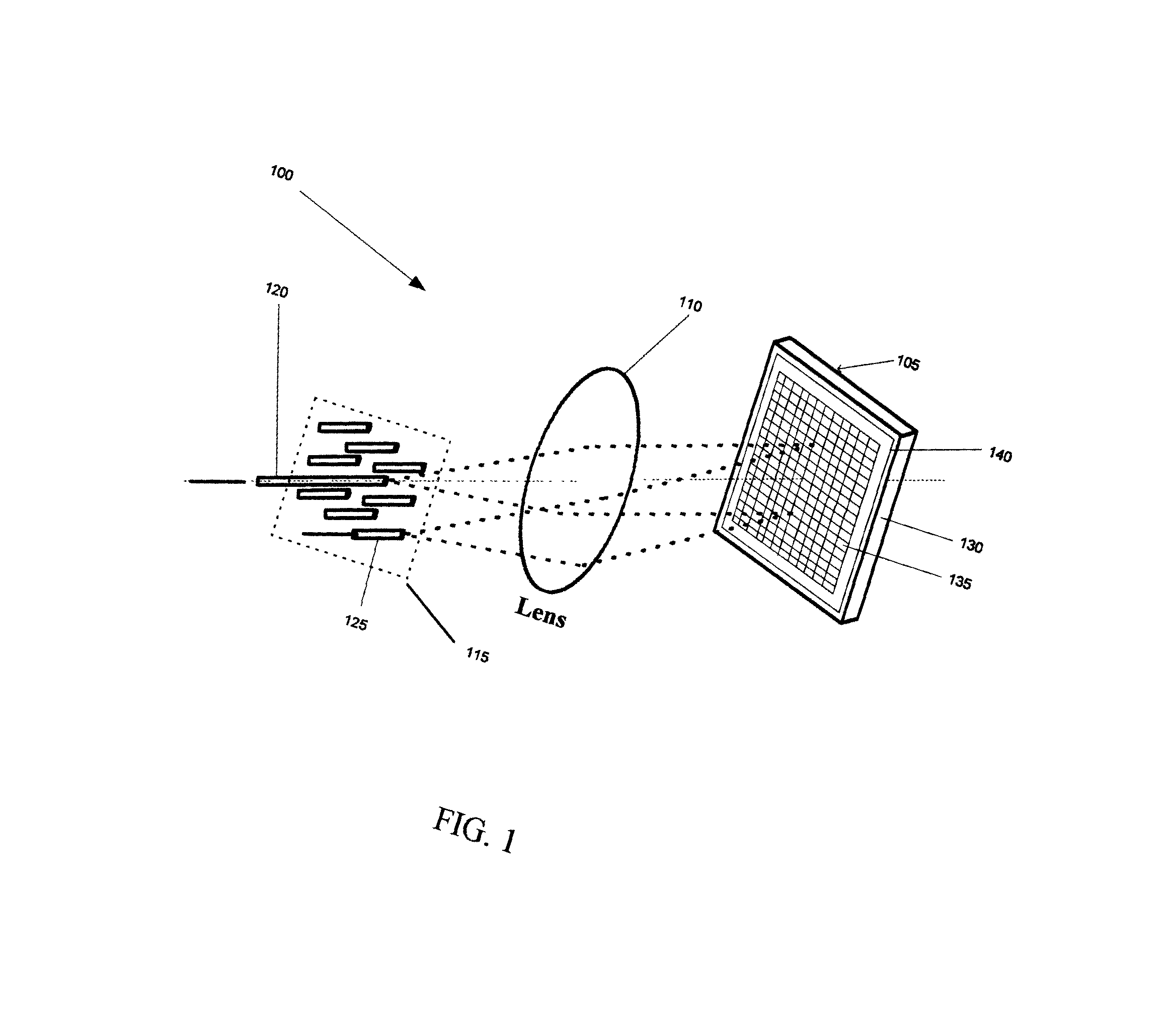
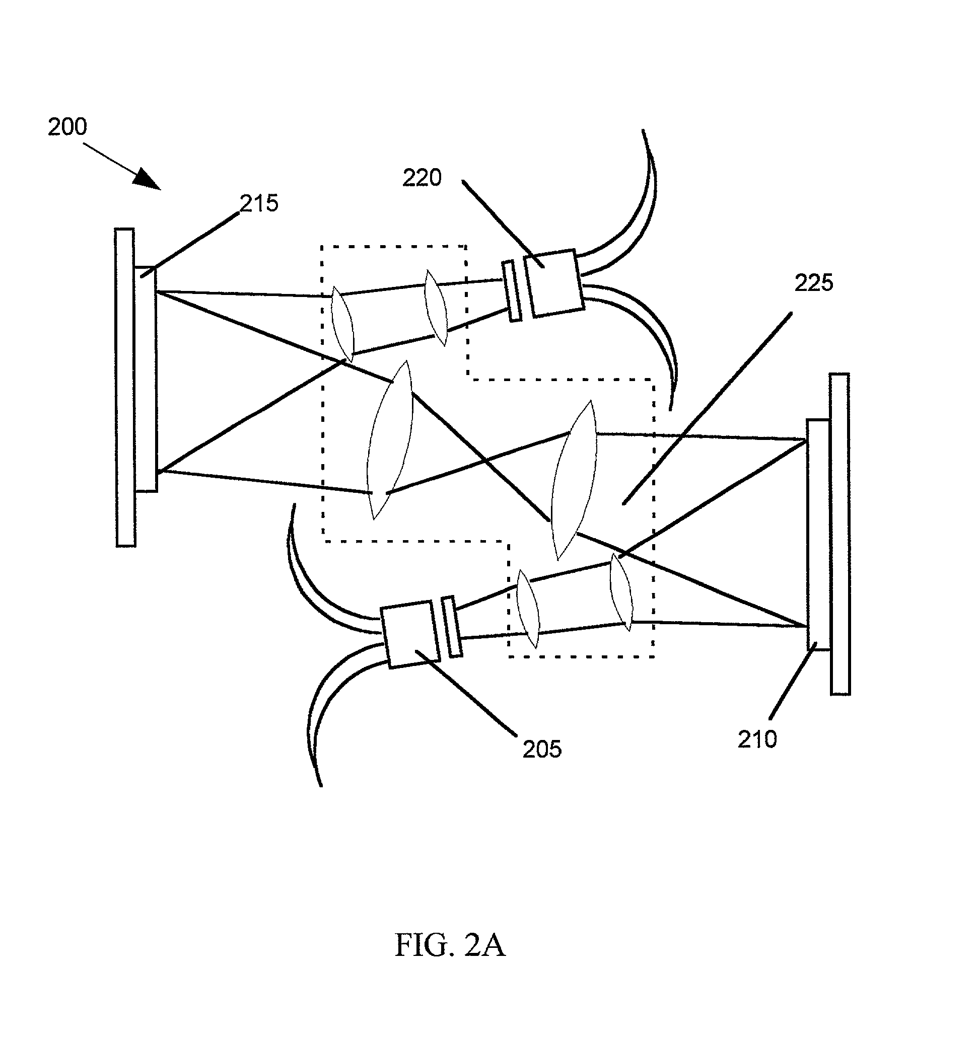
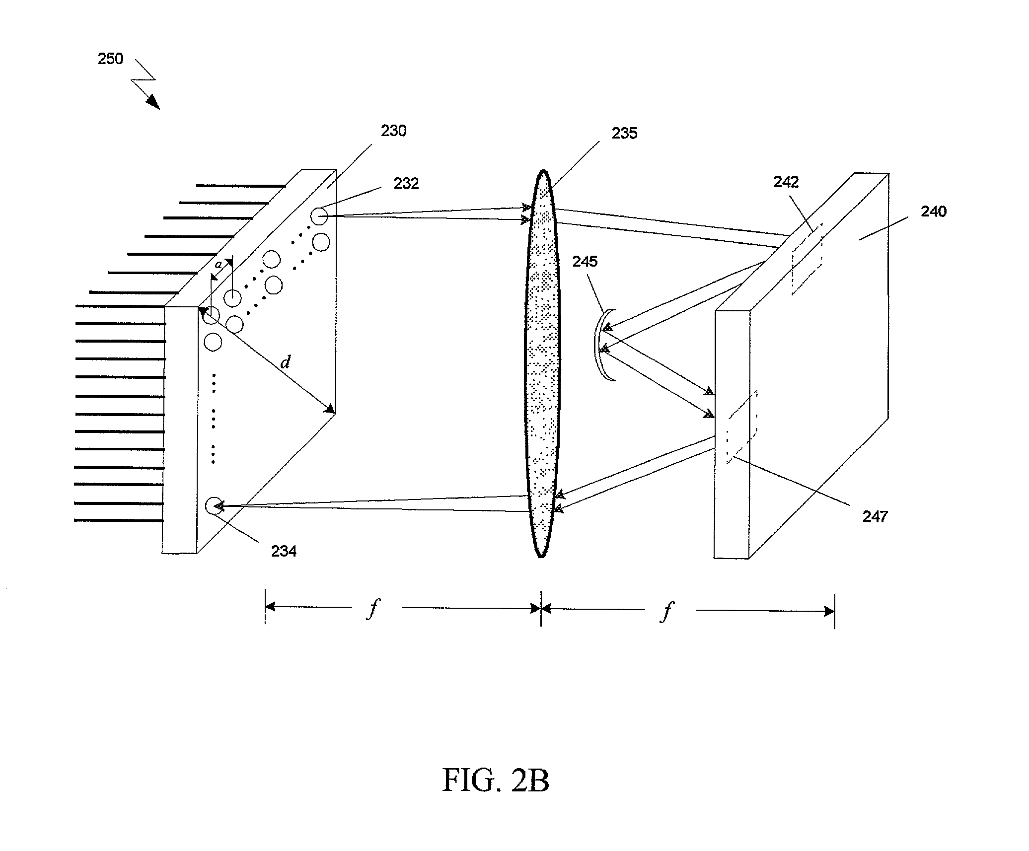
[0027] An embodiment of the present invention provides for an electro-optical component comprising (a) a substrate, (b) a phase-variable element carried on the substrate, (c) a memory carried on the substrate for storing data representative of a phase state for the phase-variable element; and (d) a controller carried on the substrate, for utilizing the data and setting the phase state for the phase-variable element. The component can be employed in an optical switch to direct light from a first port to a second port.

[0028] Another embodiment of the present invention provides for an electro-optical component comprising (a) a substrate, (b) a phase-variable element carried on the substrate, and (c) a circuit carried on the substrate for computing a phase state for the phase-variable element. This component can also be employed in an optical switch to direct light from a first port to a second port.

[0029] In another embodiment, the optical switch includes (a) a substrate, (b) a liquid ...


PUM


Abstract

There is provided an electro-optical component comprising (a) a substrate, (b) a phase-variable element carried on the substrate, (c) a memory carried on the substrate for storing data representative of a phase state for the phase-variable element; and (d) a controller carried on the substrate, for utilizing the data and setting the phase state for the element. There is also provided an electro-optical component comprising (a) a substrate, (b) a phase-variable element carried on the substrate, and (c) a circuit carried on the substrate for computing and applying a phase state for the phase-variable element.

Description

[0001] The present application is claiming priority of U.S. Provisional Patent Application Serial No. 60 / 206,074 filed on May 22, 2000.BACKGROUND OF THE INVENTION 1. Field of the Invention[0002] The present invention relates to an electro-optical component having a reconfigurable phase state. The component is particularly suitable for steering an optical beam. Such a component can be used in applications such as metropolitan area network (MAN) optical terabit switching / routing, all-optical cross-connect systems for dense wave division multiplexing (DWDM) networks, photonics signal processing, and free space laser communication.[0003] 2. Description of the Prior Art[0004] One of the most critical elements within the framework of optical transport networks based on wavelength-division multiplexing is an optical cross-connect (OXC). This optical routing device provides network management in the optical layer, with potential throughputs of terabits per second. An optical cross connectio...

Claims


Application Information

Patent Timeline
IPC IPC(8): G02B6/35G02F1/136G02F1/29G02F1/31G03H1/08
CPCG02B6/3556G02F1/136G02F1/292G02F1/31G03H1/0005G03H1/08
Inventor CROSSLAND, WILLIAM ALDENWILKINSON, TIMOTHY DAVIDESHRAGHIAN, KAMRAN
Owner INTELLIGENT PIXELS
Learn More