
Rolling element spacer for rolling guide device

a technology of rolling guide device and rolling guide element, which is applied in the direction of gearing, mechanical equipment, hoisting equipment, etc., can solve the problems of affecting the operation of the rolling guide device itself, the relative early wear of the ball, and the possibility of disassembly and maintenance of the rolling guide device. achieve the effect of high satisfaction in both directions

Inactive Publication Date: 2001-11-08
THK CO LTD
View PDF0 Cites 15 Cited by
  • Summary
  • Abstract
  • Description
  • Claims
  • Application Information

AI Technical Summary

Benefits of technology

[0008] The present invention has been conceived taking such problems into consideration, and it is an object of the invention to provide a rolling element spacer that is highly satisfactory in both of suitability to balls and suitability to an endless circulation path by using a combination of different resin materials.
[0010] For such a rolling element spacer according to the invention, a material to mold the inner member may be selected only in consideration to contact with the balls in a sliding relationship, and a material to mold the outer member may be selected principally in consideration to its relationship with the endless circulation path. It is therefore possible to achieve satisfactory suitability to both of the balls and endless circulation path.
[0013] From the viewpoint of rigid integration of the outer member and inner member, it is preferable to use resin materials of the same type for those members, e.g., to use a thermoplastic elastomer for the outer member when a thermoplastic elastomer is used for the inner member. The use of resin materials of the same type for the inner member and outer member results not only in preferable bonding between them but also in a small difference between their thermal expansion coefficients, which makes it possible to prevent the formation of any gap between the inner member and outer member even when the temperature of the rolling element spacer is increased by a heat attributable to the friction with the balls.
[0015] Furthermore, by providing the dropout preventing section that protrudes from the edges of the ball holding seats in the arranging direction of the balls and that is kept out of contact with the spherical surfaces of the balls, it is possible to maintain the balls in a preferable state of lubrication because a lubricant can easily enter gaps between the dropout preventing section and the balls. Therefore, in order to maintain a lubricant for the rolling element spacer according to the invention more preferably, an annular groove is preferably formed between the ball holding seats and the dropout preventing section surrounding the same to be used as a lubricant reservoir. Such a configuration makes it possible to apply a lubricant to the surface of the balls continually because the lubricant that has entered the gaps between the balls and the dropout preventing section is retained in the annular groove.
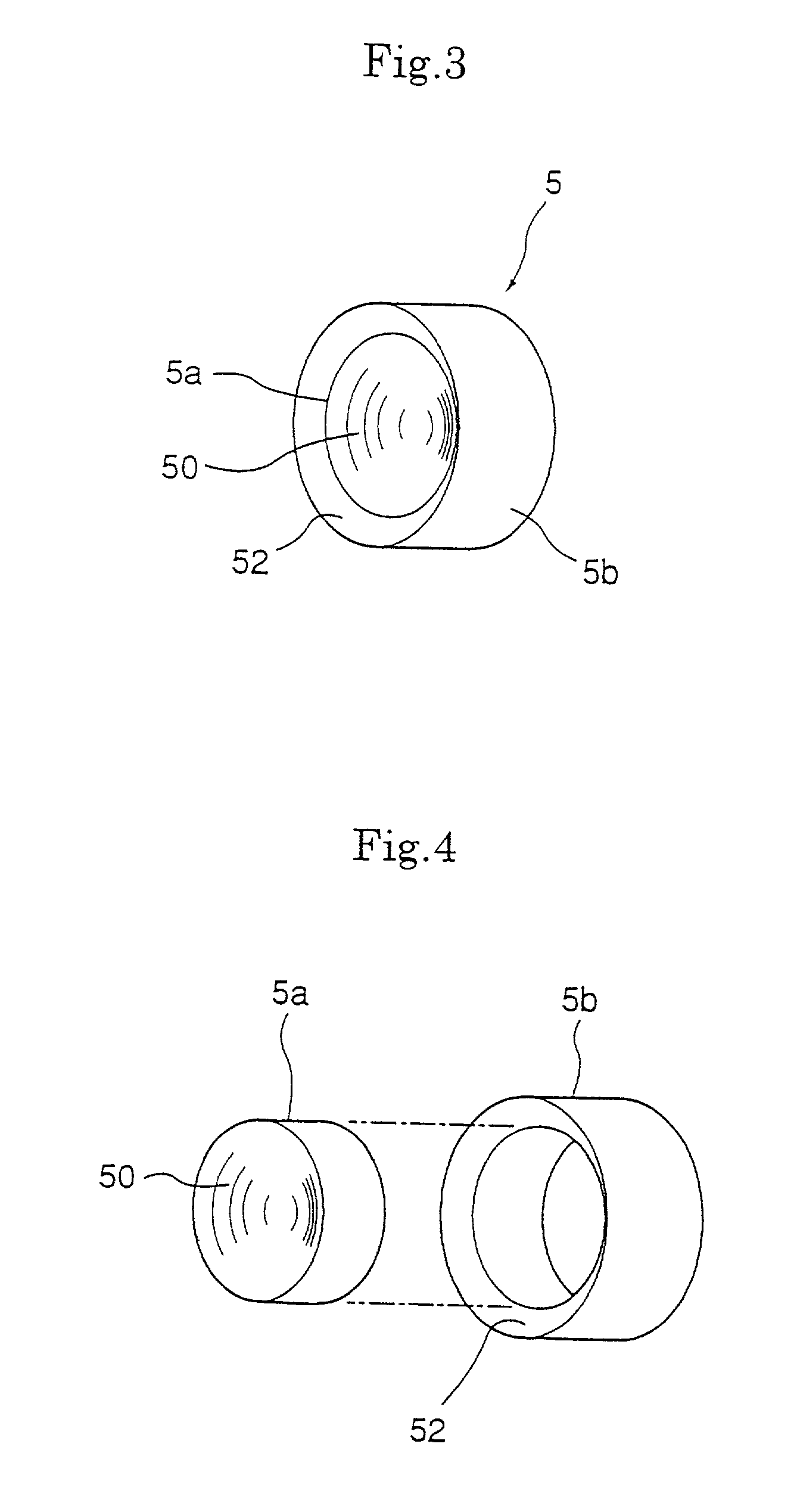
[0017] As thus described, the rolling element spacer according to the invention is constituted by a disc-shaped inner member having ball holding seats and an annular outer member covering an outer circumferential surface of the inner member, and the outer member and inner member are formed from resin materials having different flexural modulo. As a result, by forming the inner member and outer member using a combination of different resin materials, suitability to both of balls and an endless circulation path can be satisfied at a high degree.

Problems solved by technology

In such a rolling guide device, each of the balls circulating in the endless circulation path of the balls is in mutual contact with the balls located before and after the same, in the case of high speed used, for example, and this has resulted in the possibility of problems such as relatively early wear of the balls attributable to friction between the balls and burning of the balls and load rolling groove attributable to frictional heat.
Further, the arrangement of the balls is likely to become out of order in the endless circulation path when the circulating direction of the balls is reversed and, in extreme cases, this has resulted in the possibility of disablement of the operation of the rolling guide device itself as a result of the occurrence of a so-called locking phenomenon that is clogging of the balls in the endless circulation path.
Therefore, a synthetic resin material to form the rolling element spacers must be selected in consideration not only to its relationship with the balls but also to its relationship with the endless circulation path, which results in a problem in that either of contradicting properties of such a synthetic resin material must be sacrificed for the other where both of the properties are required.

Method used


Image

  • Rolling element spacer for rolling guide device
  • Rolling element spacer for rolling guide device
  • Rolling element spacer for rolling guide device

Examples


first embodiment

[0041] Both of the inner member 5a and outer member 5b are formed from synthetic resins, the materials of both of them are polyester. However, while the polyester for molding the inner member 5a has a flexural modulus of 0.055 GPa, the polyester for molding the outer member 5b has a flexural modulus of 0.157 GPa. Referring to the integration of the inner member 5a and outer member 5b, while they may be separately molded in advance and thereafter integrated by means of bonding or the like, they may be integrated by molding the outer member 5b in advance and molding the inner member 5a on an injection molding basis in a die in which the outer member 5b is inserted. During the injection molding, a melted resin may be injected into the die using the anchoring hole 55 formed on the outer member 5b as a gate, and the injection molding of the inner member in such a manner allows the locking section 54 to be automatically formed in the anchoring hole 55 and makes it possible to prevent a ga...

second embodiment

[0047] In a second embodiment of the invention, the inner member 5a is molded from a polyester having a flexural modulus of 0.157 GPa and the outer member is molded from a polyester having a flexural modulus of 0.055 GPa, as opposed to the first embodiment. Referring to the integration of the inner member 5a and outer member 5b, they may be integrated by means of bonding or the like similarly to the first embodiment and may alternatively be integrated using injection molding. In the second embodiment, however, since the inner member has a flexural modulus greater than that of the outer member, the order of injection molding is the reverse of that in the first embodiment. Specifically, the injection molding of the inner member 5a is carried out first, and the injection molding of the outer member 5b is carried out using a die in which the inner member 5a is inserted. While the injection molding of the inner member must be performed through the anchoring hole 55 of the outer member in...


PUM


Abstract

There is provided rolling element spacers that are used in a rolling guide device having an endless circulation path of balls and that are arranged to alternate with a multiplicity of balls and circulated in the endless circulation path along with the balls. They are constituted by a disc-shaped inner member having a pair of ball holding seats on which the balls slide in contact therewith and an annular outer member covering an outer circumferential surface of the inner member, and the outer member and inner member are molded from resin materials having different flexural modulo.

Description

FIELD OF THE INVENTION AND RELATED ART STATEMENT[0001] The present invention relates to rolling element spacers interposed between balls that are adjacent to each other in an endless circulation path of various rolling guide devices such as linear guide devices and ball screw devices having an endless circulation path of balls, the spacers reducing wear and heating of such balls to cause them to roll smoothly.[0002] Known conventional rolling guide devices in which a pair of members make a continuous relative motion with a series of balls in endless circulation interposed therebetween include linear guide devices that are used in a linear guide section of a machine tool, transport device or the like to guide a movable element such as a table on a fixed section such as a bed or saddle and ball screws that are used in combination with such a linear guide device to cause the movable element to make a stroke of linear motion in accordance with the quantity of rotation of a motor.[0003] ...

Claims


Application Information

Patent Timeline
Patent Type & Authority Applications(United States)
IPC IPC(8): F16C19/20F16C33/37F16H25/22
CPCF16C33/3706Y10T74/19777F16H25/2238
Inventor ABE, YASUYUKINIWA, HIROSHINISHIMURA, KENTAROUTAMURA, KIYOMI
Owner THK CO LTD
Learn More