
Error detection for data storage and transmission

a data storage and transmission technology, applied in the field of data storage and transmission error detection, can solve the problems of increasing the number of errors, the probability of the same check being given to the arithmetic sum, and the noise of the data retrieved from the tape data storage medium

Inactive Publication Date: 2001-11-01
HEWLETT-PACKARD ENTERPRISE DEV LP
View PDF4 Cites 20 Cited by
  • Summary
  • Abstract
  • Description
  • Claims
  • Application Information

AI Technical Summary

Problems solved by technology

However, this was ineffective because a C2 mis-correction will often always give the same XOR based check sum as correct data.
However, this arithmetic sum has a significant chance of giving the same check sum if a mis-correction occurs.
In the specific implementation herein, data retrieved from the tape data storage medium contains errors introduced by noise.
If the check sum at the end of the C2 correction does not detect the mis-correction, and there is more than one track in error in a track group, then it is possible that C3 correction will introduce more errors, which could be passed back as incorrect data to a user.

Method used


Image

  • Error detection for data storage and transmission
  • Error detection for data storage and transmission
  • Error detection for data storage and transmission

Examples


Embodiment Construction

[0093] There will now be described by way of example the best mode contemplated by the inventors for carrying out the invention. In the following description numerous specific details are set forth in order to provide a thorough understanding of the present invention. It will be apparent however, to one skilled in the art, that the present invention may be practiced without limitation to these specific details. In other instances, well known methods and structures have not been described in detail so as not to unnecessarily obscure the present invention.

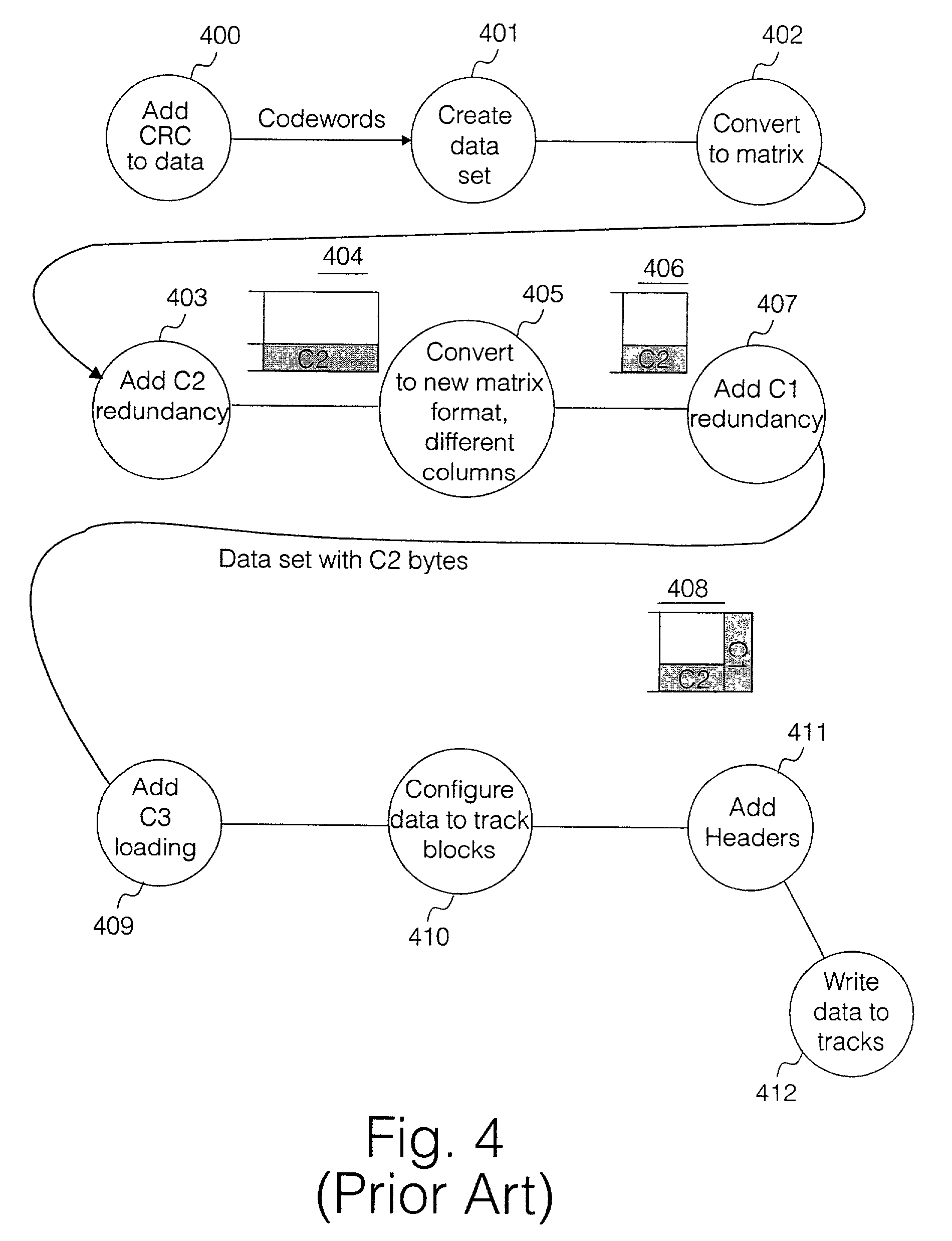
[0094] Referring to FIG. 4 herein, there is illustrated schematically a coding process applied to data prior to writing in a known DDS4 format digital data storage device. In step 400, a byte stream of user data is input into a buffer. The user data is partitioned into a set of records, each having a 4 byte check sum for protecting the record. The check sum may be checked when data is recovered during a read operation of the user dat...


PUM

PropertyMeasurementUnit
widthaaaaaaaaaa
Hamming weightaaaaaaaaaa
widthaaaaaaaaaa

Abstract

A check sum calculation on data coded with a Reed-Solomon error correcting code is performed by applying a byte based polynomial remaindering process to data bytes. The polynomial is X2+Xalpha2+alpha, over GF (28), where alpha is the primitive element GF (28) used to define redundancy coding for individual data groups. The roots of the polynomial used in the polynomial remaindering process differ from the roots of a generator polynomial of the Reed-Solomon error correcting code. The polynomial remaindering process is performed with a sub function mask containing the same mask function as used in defining redundancy coding for a data group or groups. The data group or groups are redundance coded using a Reed-Solomon code over GF (28)

Description

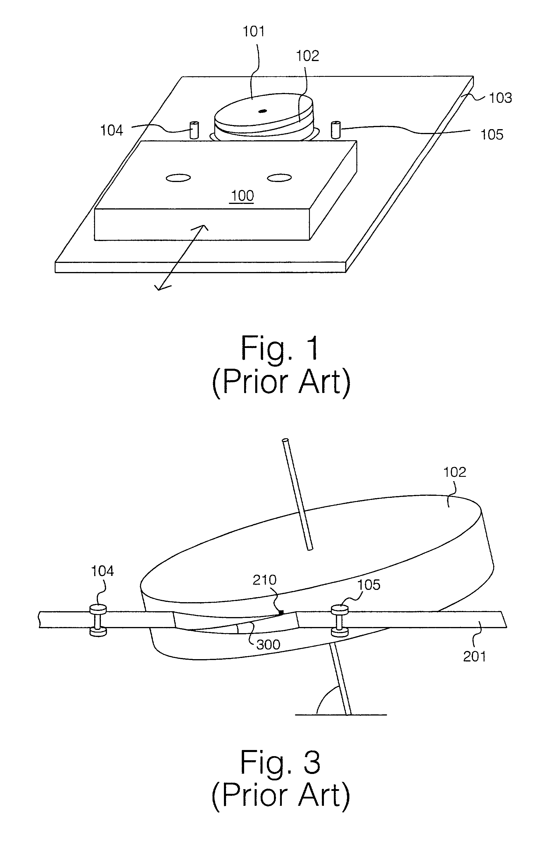
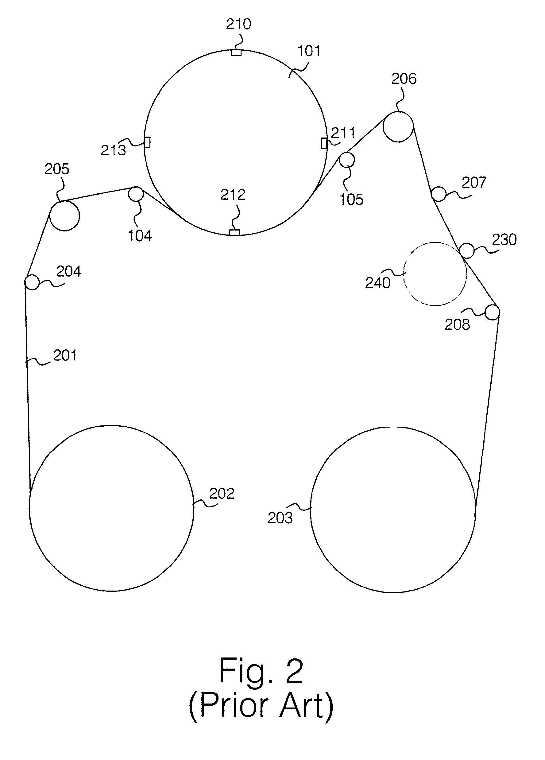
[0001] The present invention relates to the field of data handling, especially data transmission and data storage, and particularly, to a method and apparatus for detection of errors in sets of data.BACKGROUND TO THE INVENTION[0002] Conventional digital data storage (DDS) format devices provide reliable storage and retrieval of large amounts of digital data. Such devices are defined in ISO / IEEC Standard 10777:1991E.[0003] In a DDS read / write mechanism, as defined in the ISO / IEEC Standard 10777:1991E, data is recorded on an elongate tape data storage medium coated with a magnetic coating. A rotating drum carries a plurality of read heads and a plurality of write heads. The elongate band of magnetic tape is passed around the rotating drum, resulting in a plurality of physical data tracks written in parallel across the elongate band of magnetic tape between opposite edges of the tape.[0004] Referring to FIG. 1 herein, there is shown schematically a layout of a tape data storage cartrid...

Claims


Application Information

Patent Timeline
Patent Type & Authority Applications(United States)
IPC IPC(8): G11B20/18H03M13/00H03M13/09H03M13/15
CPCG11B20/1833H03M13/00H03M13/09H03M13/15
Inventor PATERSON, KENNETH GRAHAM
Owner HEWLETT-PACKARD ENTERPRISE DEV LP
Learn More