
Magnetic filter and method for purifying and treating liquids using permanent magnetic balls

Inactive Publication Date: 2001-07-05
TECH COMMLIZATION
View PDF0 Cites 9 Cited by
  • Summary
  • Abstract
  • Description
  • Claims
  • Application Information

AI Technical Summary

Benefits of technology

[0013] It is another object of the invention to provide a filter of a relatively small size that is capable of removing from the liquid all magnetic particles, non-magnetic particles of large size, and most of the particles comprising only in part of magnetic materials, all without significant pressure drop across the filter.
[0014] It is yet another object of the invention to provide a filter for purification and magnetic treatment of a liquid containing magnetic particles with substantially increased operational time so that the time until clogging of the filter and subsequently the repair or replacement intervals are significantly increased.
[0016] It is a further object of the invention to provide a filter capable of treating the passing liquid with a magnetic field. For applications such as a fuel filter for the internal combustion engine, treating the fuel with magnetic field improves the process of atomization down the line. Water or other non-magnetic liquid can also be treated with a strong magnetic field to achieve various advantages described above such as for prevention of scale deposits or for preparation of concrete.
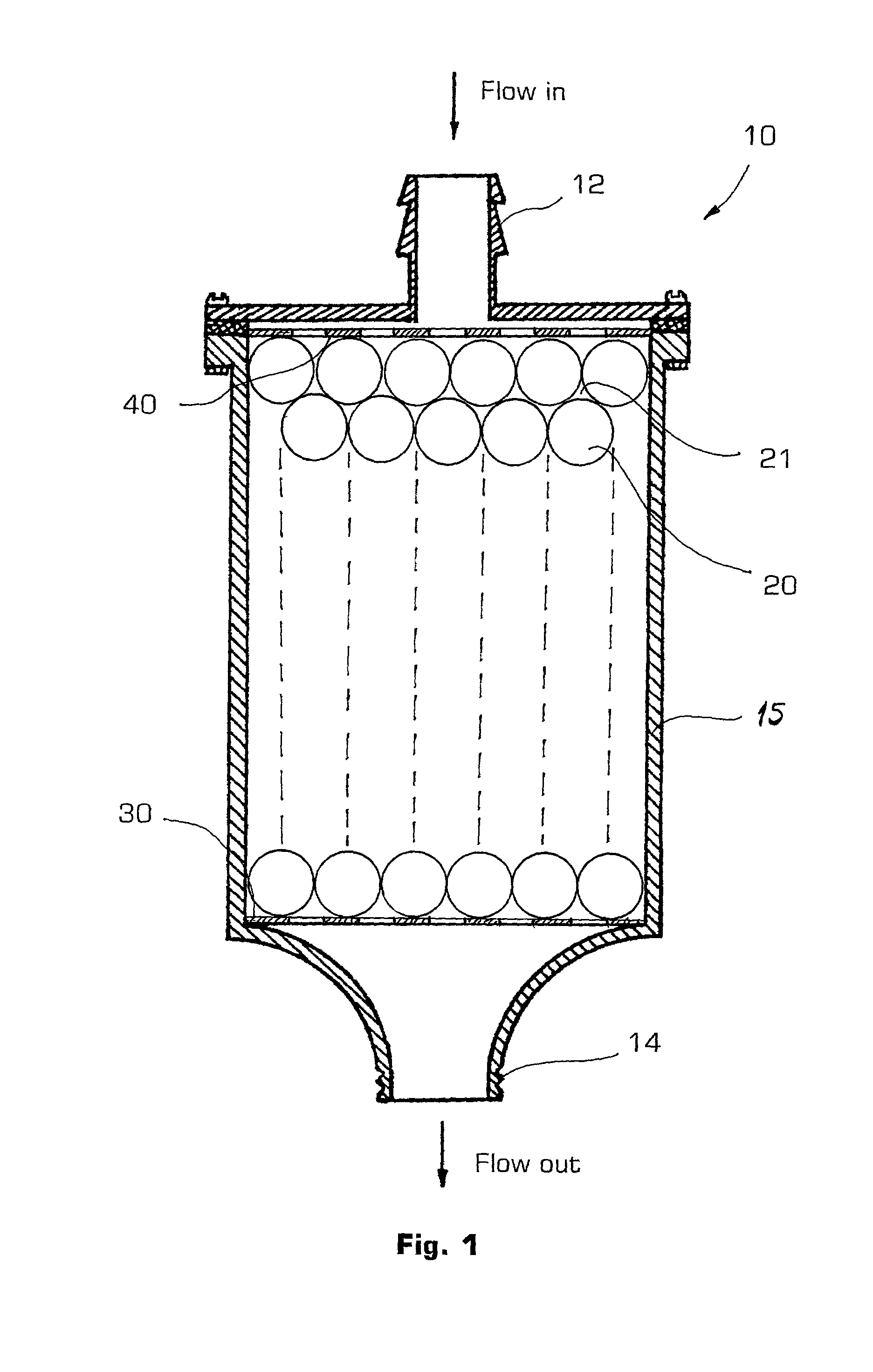
[0019] The polarity orientation of each magnet may be random but it is preferred to orient them all in the same direction for further improvement of the filtering efficiency. The best orientation of magnetic field is that which is perpendicular to the direction of the flow. That in itself promotes the secondary effect of the filter which is treating the passing liquid with a strong magnetic field and lowering its viscosity and improving atomizing properties. The plurality of magnetic balls may be typically placed in a housing made preferably of steel or other soft magnetic metals to close the magnetic field loops and conduct it throughout the body of the filter. In one embodiment, all magnetic balls have the same diameter and are packed tightly in a housing having an inlet and an outlet for the passing liquid. In a variation of this embodiment, the spaces between the magnetic balls are filled with a number of magnetic or soft-magnetic balls of progressively smaller diameter to increase the efficiency of the liquid purification without causing substantial pressure drop across the filter. It is preferred in that case to select the smaller magnetic balls to have a diameter of about 0.15 of the diameter of the bigger magnetic balls.
[0021] After entering the filter of the present invention, the flow of liquid is passing through the body of the filter containing magnetic balls that create a magnetic field with strong magnetic intensity. Since magnetic balls are packed in such a way that there is no direct path for the liquid flow, it is subjected to multiple turns around the magnetic balls which creates excellent mixing conditions and promotes adhesion of all magnetic particles to the surfaces of the magnetic balls. Other particles such as mixed contaminants having some of magnetic contents as well as the larger non-magnetic particles with the size bigger than the space between the magnetic balls would also be trapped inside the filter. Independently of the filtration process, the strong magnetic field increases the atomization properties of the liquid, reduces temporarily its viscosity, improves the mixing of all the liquid components and additives and may reduce its surface tension. All of these effects are useful in such cases where such treated liquid fuel then proceeds further down the line to the atomizer of the engine so that the ignition and burning characteristics are improved. As the filter accumulates magnetic particles, the spaces between the magnetic balls are reduced but due to the unobstractive geometry of the plurality of magnetic balls the flow resistance is not increased to any significant degree until the filter is about 70% clogged. In other words, the geometry of a plurality of spheres allows for increased operational time of the filter. In our tests with the fuel filters for an automobile, the service life of the filter of the present invention was increased (as measured by the automobile travel distance) from about 15,000 miles to about 50,000 miles.

Problems solved by technology

In the second type of the filters, energizing the coil causes metallic inserts to propagate the magnetic field inside the body of the filter and attract metallic contaminants from passing liquid.
Another disadvantage of electromagnetic coils is the constant need to apply electrical power for the filter to operate, a major contributor to operating expenses and also a source of possible failures, especially in critical applications.
Even during momentary interruption of electrical power, the risk exists of sudden release of all trapped material into the flow of liquid with possible catastrophic consequences for the rest of the hydraulic system.
There is a need therefore to provide such systems with additional normally closed type valves designed to block the flow of liquid during unexpected power failures, creating added costs and maintenance concerns.
There is also a need for an expensive solenoid type coil to be a part of the filter design.
A further disadvantage is the lack of flexibility in arranging the orientation of magnetic field of each individual ball inside the filter.
Changing that orientation is technically very difficult.
These and other filters have inherent disadvantages, caused by the shape and placement of the magnetic elements.
In addition, as the filter of such design accumulates magnetic particles, the resistance to liquid flow increases so as the danger of dislodging the magnetic particles previously accumulated and their undesirable release back into the liquid flow.
A limitation of this device is the irregular shape of the magnetite elements which prevents uniform and consistent exposure of water to the magnetic field.
As the filter accumulates magnetic particles, the spaces between the magnetic balls are reduced but due to the unobstractive geometry of the plurality of magnetic balls the flow resistance is not increased to any significant degree until the filter is about 70% clogged.

Method used


Image

  • Magnetic filter and method for purifying and treating liquids using permanent magnetic balls

Examples


Embodiment Construction

[0026] A detailed description of the most preferred embodiment of the present invention follows with reference to accompanying drawing on FIG. 1 in which like elements are indicated by like reference numerals.

[0027] According to the design and the method of the present invention, the filter (10) consists of a housing (15) having the flow inlet (12) and the outlet (14). Both inlet and outlet may be configured as a barbed connector as shown for example for the inlet (12). Alternately, as shown for the outlet (14), it may be configured as having attachment threads to connect to the lines of the rest of a hydraulic system. Multiple variations of the filter housing and attachments can be used for the filter of the present invention as can be readily apparent to the skilled in the art.

[0028] The housing (15) of the filter (10) contains a plurality of magnetic balls (20) having spaces (21) therebetween and located between two optional perforated plates (30) and (40). The purpose of plates ...


PUM

PropertyMeasurementUnit
Diameteraaaaaaaaaa
Diameteraaaaaaaaaa
Timeaaaaaaaaaa

Abstract

A filter for and a method of removal of magnetic particles and treating a liquid with a magnetic field in which a liquid flows through a filter containing permanent magnetic balls tightly packed together so that there is no straight flow path through the filter but only around these magnetic balls. Increased mixing and turbulence of flow coupled with strong intensity of a magnetic field across the direction of the flow promotes better attraction and retention of magnetic particles on the magnetic balls. The filter is particularly useful as a fuel or oil filter for an internal combustion engine. Other advantageous applications include water treatment filters. The filter is capable of removing magnetic particles for an extended period of time without clogging.

Description

CROSS-REFERENCE DATA[0001] This is a continuation-in-part of the patent application No. 09 / 419,498 filed Oct. 18, 1999 which is incorporated herein by reference in its entirety.[0002] 1. Field of the Invention[0003] The present invention relates generally to a magnetic filter and method for purifying various liquids containing magnetic particles, such as fuels, lubricants, water, hydraulic fluids, and cooling liquids among others. Specifically, the invention relates to filters employing internal magnetic elements in the shape of permanent magnetic balls to trap such magnetic particles and subject the passing by liquid to strong magnetic fields. The filter of the present invention can be used with particular success as a stand alone disposable fuel or oil filter or in combination with other filters for a device with limited energy resources such as an internal combustion engine, as well as in applications such as cooling devices for nuclear and other reactors, etc.[0004] 2. Descripti...

Claims


Application Information

Patent Timeline
IPC IPC(8): B01D27/06B01D35/06B03C1/28F01P11/06
CPCB01D27/06B01D35/06B03C1/28B03C2201/18F01P11/06F01P2011/061B03C1/0332B03C1/286B03C1/30
Inventor TULCHINSKIY, LEONID
Owner TECH COMMLIZATION
Learn More