Injection apparatus for melted metals

a technology of injection apparatus and metal, which is applied in the direction of clay mixing apparatus, rotary stirring mixer, mixer, etc., can solve the problems of unstable metering, difficulty in material transfer by screw rotation, and maintenance of the temperature of melted metal in liquid phas

Inactive Publication Date: 2001-06-28
NISSEI PLASTIC IND CO LTD
View PDF0 Cites 15 Cited by
  • Summary
  • Abstract
  • Description
  • Claims
  • Application Information

AI Technical Summary

Benefits of technology

[0020] In the construction stated above, a reservoir for the metals in liquid phase is provided between the plunger as a fore end portion and a feeding portion. By means of retracting the injection screw the metals temporarily reserved in the reservoir is allowed to be reserved in the above-mentioned metering chamber. Thereby, the next feed of metals is completely melted and the temperature thereof is maintained while they are maintained in the reservoir even if the metals are melted by the external heat. As a result, the temperature of metals can be kept constant.
[0022] Furthermore, in the construction stated above, while the screw moves forward and the feeding opening is being closed with the axis, the feeding of the metals will be automatically limited upon the start of injection. It prevents congestion of the metals in the screw grooves in the rear of the screw. Thereby, a friction by rotation and sliding to the screw is decreased, which stabilizes melting and injecting of the metals to improve the quality of molded products.
[0023] The heating cylinder is inclined downward so as to reserve the melted metals in the reserving space surrounding the axis in the front portion of the heating cylinder. Therefore, even if the metals are in the liquid phase of a low viscosity, they will not flow backward so that the reserved amount will not fluctuate. In addition to it, since the rotation of the screw supplies the metals in liquid phase, in spite of injection molding the metals in liquid phase, a stable quality of molded metal products can be produced.

Problems solved by technology

Problems occurring in case of adopting the foregoing injection molding for the metals are, for example, difficulty on the transfer of the material by means of rotation of the screw, the maintenance of the temperature of the melted metals in liquid phase, unstable metering, or the like.
Hence, a transfer force such as the one produced with the melted plastic material by means of rotation of the screw is not readily produced.
Nevertheless, as the metals are further melted, the viscosity thereof drops with an increasing ratio of the liquid phase, and the transfer force produced by the screw grooves between the adjacent screw flights decreases, thereby making it difficult to supply the melted metals in a stable manner to the fore end portion of the heating cylinder by means of rotation of the screw.
However, the metals in the low-viscous liquid phase cannot produce a pressure high enough to push the screw backward.
Thus, the screw retraction by the material pressure hardly occurs, and if the metals are reserved in the fore end portion by means of rotation of the screw alone, a quantity thereof undesirably varies, thereby making it impossible to meter a constant quantity each time.
This poses a problem that the granular material supplied from the feeding opening provided behind the weir cannot be transferred readily by means of rotation of the screw.
Furthermore, in the construction stated above, while the screw moves forward and the feeding opening is being closed with the axis, the feeding of the metals will be automatically limited upon the start of injection.

Method used


Image

  • Injection apparatus for melted metals
  • Injection apparatus for melted metals
  • Injection apparatus for melted metals

Examples


Embodiment Construction

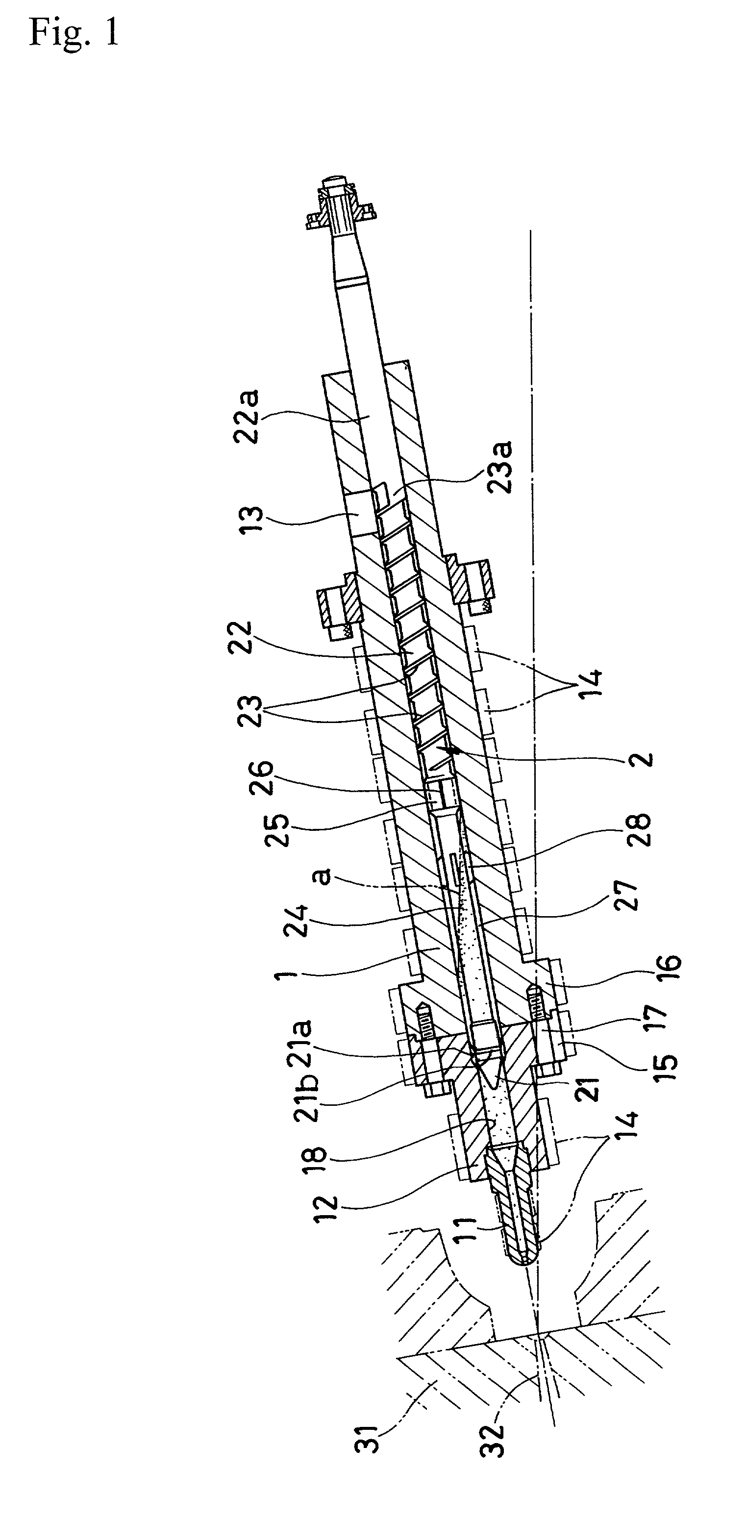
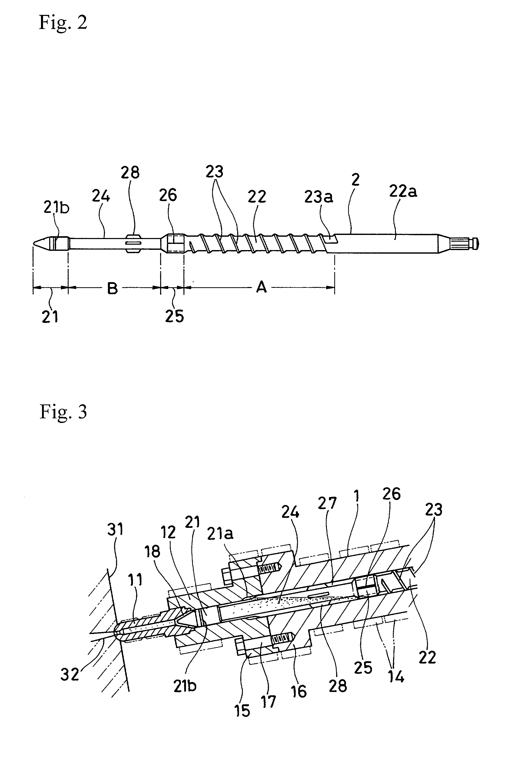
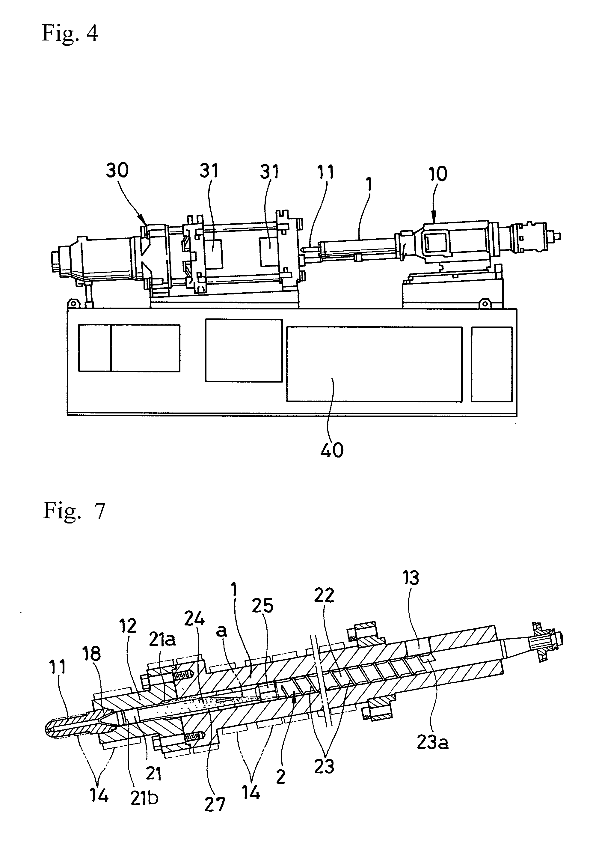
[0032] The figures show one embodiment of the injection apparatus according to the present invention and reference numeral 1 denotes a heating cylinder, and reference numeral 2 denotes an injection screw installed within the heating cylinder 1.

[0033] The heating cylinder 1 is provided with a fore end member 12 to which a nozzle member 11 is screwed on the end thereof, and has a feeding opening 13 on the rear part thereof for feeding the granular metals. On the circumference of the heating cylinder 1 from the nozzle member 11 and the fore end member 12 to the feeding opening 13, band heaters 14 are provided at regular intervals.

[0034] The fore end member 12 is mounted to the heating cylinder 1 as a fore end portion by mating a flange 15 formed in the rear end of the fore end member 12 with a flange 16 formed in the end of the heating cylinder 1, and fixed with bolts 17. The internal diameter of the front member 12 communicating with the nozzle member 11 is smaller than that of the he...


PUM

PropertyMeasurementUnit
Weightaaaaaaaaaa
Diameteraaaaaaaaaa

Abstract

An injection apparatus for melted metals is provided to be capable of transferring the metals, melting them by the external heat, metering and degassing by employing a reservoir to reserve metals in liquid phase for the injection screw. The injection apparatus comprises a heating cylinder having a fore end portion which communicates with a nozzle member and of which internal diameter is made smaller to serve as a metering chamber, and an injection screw installed within the heating cylinder to be movable and rotational. A tip end of the injection screw is formed in a plunger having a diameter that can insert into the metering chamber with keeping a clearance for sliding. A reservoir, for reserving melted metals in liquid phase, consisting of an axis is provided between the plunger and a feeding portion containing screw flight around the axis. A projected portion for limiting the feeding of granular metals flowing to the reservoir and for preventing the metals in liquid phase from flowing backward during injection is provided on a boundary between the feeding portion and the reservoir.

Description

[0001] 1. Field of the invention[0002] The present invention relates to an injection apparatus for melted metals used for injection molding nonferrous metals having a low melting point, such as zinc, magnesium, or alloy thereof, completely melted in liquid phase.[0003] 2. Detailed Description of the Prior Art[0004] Attempts have been made to completely melt nonferrous metals having a low melting point so as to allow injection molding in liquid phase. Like in the case of injection molding of plastics, the molding method adopts a heating cylinder having inside an injecting screw, which is allowed to rotate and move along the axial direction. Granular metals supplied from the rear portion of the heating cylinder are heated and melted completely by shear heat and external heat while being transferred toward the fore end of the heating cylinder by means of rotation of the screw. After a quantity of the melted metals in liquid phase is metered in the fore portion of the heating cylinder, ...

Claims


Application Information

Patent Timeline
IPC IPC(8): B22D17/04B22D17/20B22D17/30
CPCB22D17/04B22D17/203B22D17/2061
Inventor KODA, TOSHIYASUMIYAGAWA, MAMORUHAYASHI, YUJI
Owner NISSEI PLASTIC IND CO LTD
Why Eureka
Try Eureka