
Short pitch tooth chain

a technology of short-pitch tooth and chain, applied in the field of chain arts, can solve the problem of sound generation as the major source of noise, and achieve the effect of reducing noise levels and reducing noise levels

Inactive Publication Date: 2001-05-03
MESH CO LLC THE +1
View PDF0 Cites 2 Cited by
  • Summary
  • Abstract
  • Description
  • Claims
  • Application Information

AI Technical Summary

Benefits of technology

10. One advantage of the present invention is the provision of a short pitch tooth chain which reduces noise levels by increasing the frequency at which the chain meshes with a sprocket to a level which is inaudible, or at least less audible to the human ear.
is the provision of a short pitch tooth chain which reduces noise levels by increasing the frequency at which the chain meshes with a sprocket to a level which is inaudible, or at least less audible to the human ear.
11. Another advantage of the present invention is the provision of a short pitch tooth chain having a chain pitch value which is approximately twice a sprocket chordal pitch value.
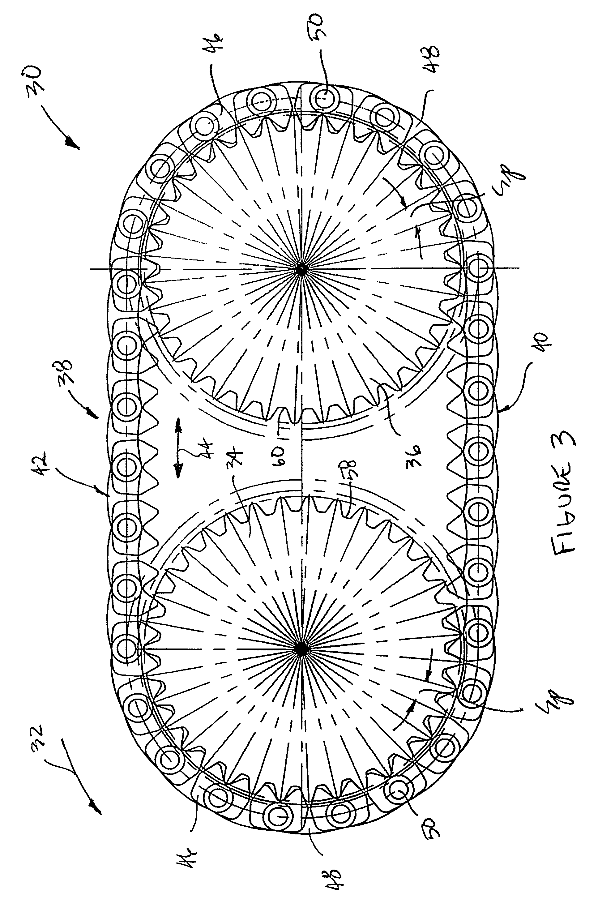
12. A further advantage of the present invention is the provision of a chain system having a short pitch tooth chain that reduces noise levels by increasing the frequency at which the chain meshes with a sprocket to a level which is inaudible, or at least less audible to the human ear.
13. Yet another advantage of the present invention is the provision of chain system having a short pitch tooth chain with a chain pitch value which is approximately twice a sprocket chordal pitch value.

Problems solved by technology

3. Drive chain systems and timing chain systems incorporating known chains such as inverted tooth chains and roller chains have several components of undesirable noise.
A major source of noise is the sound generated as the chain engaging members, such as inverted teeth or rollers, leave the span and collide with a sprocket during meshing.

Method used


Image

  • Short pitch tooth chain
  • Short pitch tooth chain
  • Short pitch tooth chain

Examples


Embodiment Construction

)

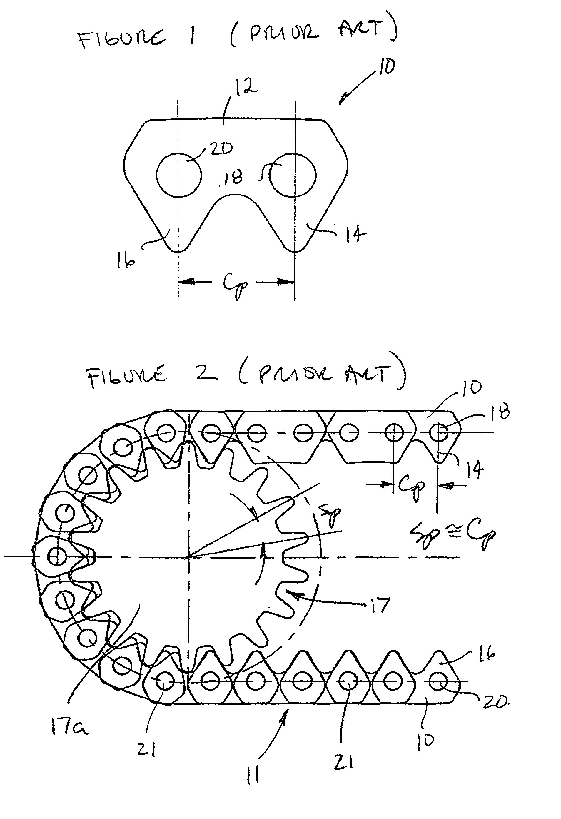
43. With reference to FIGS. 1 and 2, a conventional double-toed link 10 for a known inverted tooth chain 11 includes a body portion 12 having a first toe 14 spaced from a second toe 16. The toes 14, 16 consecutively engage adjacent and mutually conforming tooth spaces 17 associated with a sprocket 17a. The link 10 also includes a first aperture 18 and a second aperture 20 spaced apart from the first aperture. The apertures 18, 20 receive conventional pins 21 for joining together a number of different links, including links 10, to form the known inverted tooth chain 11.

44. The link 10 has a chain or link pitch C.sub.p conventionally defined as the distance between the centers of the first and second apertures 18, 20. It should be appreciated that a sprocket used in conjunction with the link 10 has a sprocket chordal pitch S.sub.p (conventionally defined as the distance separating adjacent teeth or tooth spaces) substantially equal to the chain pitch C.sub.p. Thus, for conventional c...


PUM


Abstract

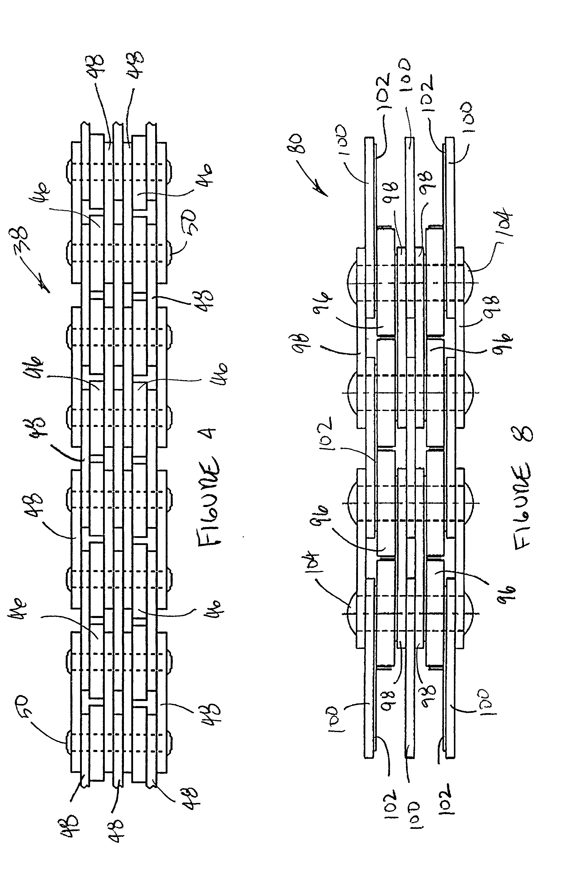
A short pitch tooth chain that reduces the level of impact noise generated during operation is disclosed. A chain system includes a first sprocket having a plurality of sprocket teeth spaced apart by a first distance, a second sprocket also having a plurality of sprocket teeth spaced apart by the first distance, and a short pitch tooth chain wrapped around the first and second sprockets. The short pitch tooth chain includes a first link having a first aperture spaced from a second aperture by a second distance, a second link having a first toe spaced from a second toe by the first distance, the second link having a third aperture and being connected to the first link by a first pin extending through the first and third apertures, and a third link having a third toe spaced from a fourth toe by the first distance, the third link having a fourth aperture and being connected to the first link by a second pin extending through the second and fourth apertures. The first distance defines a sprocket chordal pitch and the second distance defines a chain pitch wherein the chain pitch is about twice the sprocket chordal pitch.

Description

CROSS REFERENCE TO RELATED APPLICATIONS1. This application claims the benefit of U.S. Provisional Patent Application Ser. No. 60 / 074,252, filed Feb. 10, 1998.BACKGROUND OF THE INVENTION2. The present invention relates to the chain arts, and in particular, a short pitch tooth chain that provides improved noise reduction over conventional tooth chains.3. Drive chain systems and timing chain systems incorporating known chains such as inverted tooth chains and roller chains have several components of undesirable noise. A major source of noise is the sound generated as the chain engaging members, such as inverted teeth or rollers, leave the span and collide with a sprocket during meshing. The resulting impact noise is repeated with a frequency generally equal to that of the frequency of the chain meshing with the sprocket. It is known that the impact noise levels associated with chains can be reduced by altering the engagement geometry of the chain and / or sprocket to, in part, reduce the...

Claims


Application Information

Patent Timeline
IPC IPC(8): F16G13/04
CPCF16G13/04
Inventor REBER, REINHOLD FRIEDRICH
Owner MESH CO LLC THE
Learn More