
Battery having a temperature control structure and use of such a battery

Active Publication Date: 2022-11-08
ROBERT BOSCH GMBH
View PDF12 Cites 0 Cited by
  • Summary
  • Abstract
  • Description
  • Claims
  • Application Information

AI Technical Summary

Benefits of technology

The invention allows for individual components of a battery to have their temperature control adjusted based on their specific needs. By using two temperature-controlling fluid chambers, multiple battery cells and components of the electronic power system can have separate temperature control optimized. This process helps to further improve the overall performance of the battery.

Problems solved by technology

Furthermore, the battery cells of a battery module, such as for example lithium ion battery cells or lithium polymer battery cells, heat up during operation as a result of chemical conversion processes due to their electrical resistance during power output or power input.

Method used


Image

  • Battery having a temperature control structure and use of such a battery
  • Battery having a temperature control structure and use of such a battery
  • Battery having a temperature control structure and use of such a battery

Examples


Embodiment Construction

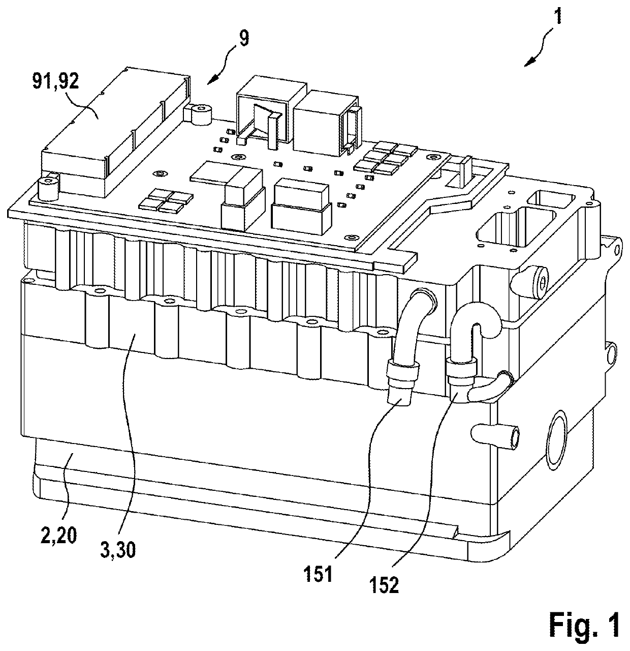
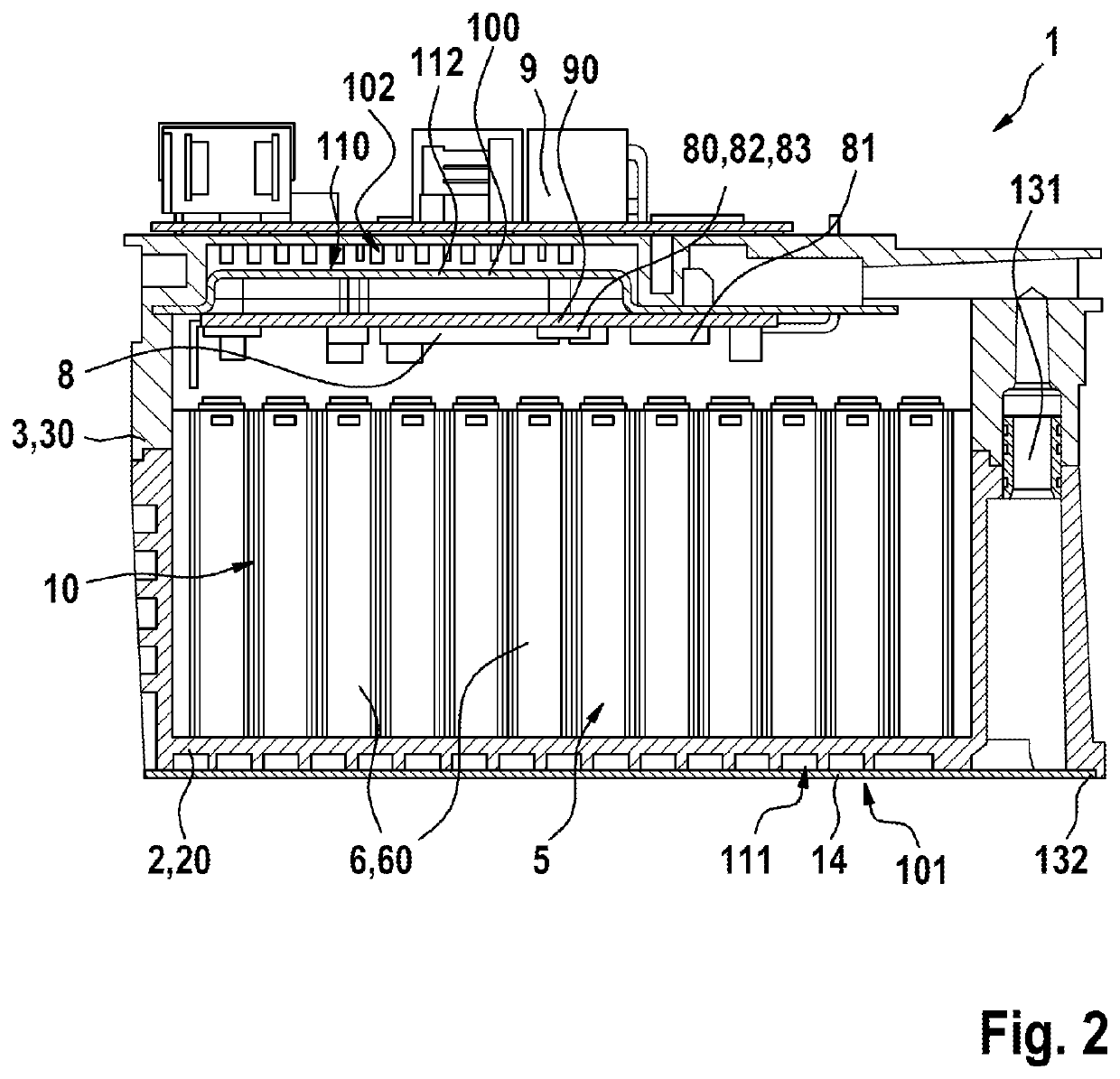
[0062]FIG. 1 illustrates a perspective view of one embodiment of a battery 1 in accordance with the invention. FIG. 2 illustrates a sectional view of this embodiment in accordance with the invention of the battery 1 in accordance with FIG. 1. The FIGS. 1 and 2 are now to be described jointly.

[0063]The battery 1 comprises a first housing element 2 and a second housing element 3. In accordance with the embodiment of the battery 1 illustrated in FIGS. 1 and 2, the first housing element 2 is embodied as a die-cast housing 20 and the second housing element 3 is embodied as a die-cast housing 30.

[0064]The first housing element 2 and the second housing element 3 jointly form an inner chamber 5 for receiving a battery module 10. The inner chamber 5 and the battery module 10 are apparent in particular in the sectional view in accordance with FIG. 2. In particular, the first housing element 2 and the second housing element 3 are embodied in a fluid-tight manner connected to one another. For t...


PUM

PropertyMeasurementUnit
temperatureaaaaaaaaaa
electrically conductiveaaaaaaaaaa

Abstract

A battery comprising a first housing element (2) and a second housing element (3) that jointly form an inner chamber (5) for receiving a battery module (10), wherein the second housing element (3) forms a second temperature control structure (102) on a face that is facing the inner chamber (5) and in particular is facing the first housing element (2), and a cover element (100) is connected to the second housing element (3) in such a manner that a temperature-controlling fluid receiving device (112) through which temperature-controlling fluid can flow is delimited by the cover element (100) in a fluid-tight manner with respect to the inner chamber (5) and the second temperature control structure (102) is embodied in such a manner that the temperature-controlling fluid can flow around it.

Description

BACKGROUND OF THE INVENTION[0001]The invention is based on a battery comprising a first housing element and a second housing element that jointly form an inner chamber for receiving a battery module, wherein a plurality of battery cells of the battery module that are interconnected to one another in series and / or parallel in an electrically conductive manner is arranged in the inner chamber, wherein the battery cells are embodied in particular in a prismatic manner and furthermore a first element of a battery control system is arranged in the inner chamber, wherein the first housing element forms a first temperature control structure on a face that is remote from the inner chamber and in particular is remote from the second housing element. Subject matter of the present invention is also the use of such a battery.[0002]It is known from the prior art that a battery module comprises a plurality of individual battery cells that each comprise a positive voltage tap and a negative voltag...

Claims


Application Information

Patent Timeline
Patent Type & Authority Patents(United States)
IPC IPC(8): H01M50/20H01M10/63H01M10/647H01M10/653H01M10/6567H01M10/42
CPCH01M50/20H01M10/425H01M10/63H01M10/647H01M10/653H01M10/6567H01M10/613H01M10/615H01M10/625H01M10/6568H01M10/6563H05K7/20145H05K7/20272B60L58/26H01M10/60H01M10/655H01M2220/20B60L50/64Y02T10/70Y02E60/10
Inventor SCHMITT, MARKUSKOPP, BENJAMIN
Owner ROBERT BOSCH GMBH
Learn More