Antenna module and communication device equipped with the same

a technology of communication device and antenna module, which is applied in the direction of individual energised antenna array, substantially flat resonant element, resonant antenna, etc., can solve the problem of narrowing the frequency band width of the antenna

Active Publication Date: 2022-09-20
MURATA MFG CO LTD
View PDF9 Cites 0 Cited by
  • Summary
  • Abstract
  • Description
  • Claims
  • Application Information

AI Technical Summary

Benefits of technology

The patent aims to improve the performance of antennas by reducing the dielectric constant of the substrate it is mounted on. The invention achieves this by creating space between the substrate and the ground electrode, which helps to decrease the effective dielectric constant and reduce signals lost during transmission. This results in a wider band width and greater efficiency of the antenna.

Problems solved by technology

However, when a dielectric substrate is thinned, there may arise a problem that the frequency band width of the antenna is narrowed.

Method used


Image

  • Antenna module and communication device equipped with the same
  • Antenna module and communication device equipped with the same
  • Antenna module and communication device equipped with the same

Examples


first embodiment

[0039](Basic Configuration of Communication Device)

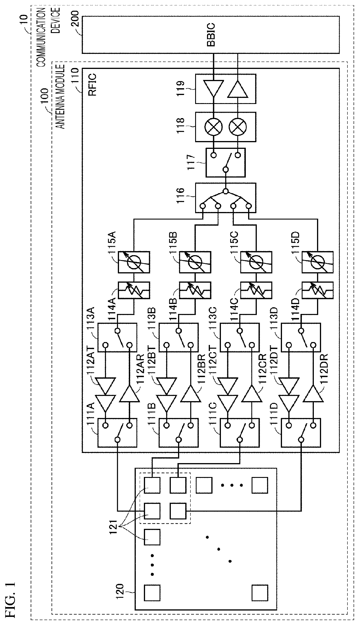
[0040]FIG. 1 is a block diagram of an example of a communication device 10 to which an antenna module 100 according to the embodiment is applied. The communication device 10 is, for example, a mobile terminal such as a cellular phone, a smart phone, a tablet or the like, or a personal computer having a communication function.

[0041]Referring to FIG. 1, the communication device 10 includes the antenna module 100 and a BBIC 200, which constitutes a baseband signal processing circuit. The antenna module 100 includes a radio frequency integrated circuit (RFIC) 110, which is an example of a radio frequency element, and an antenna array 120. The communication device 10 up-converts a signal transmitted from the BBIC 200 to the antenna module 100 into a radio frequency signal so as to radiate the converted signal through the antenna array 120, and down-converts a radio frequency signal received by the antenna array 120 and performs signal pr...

second embodiment

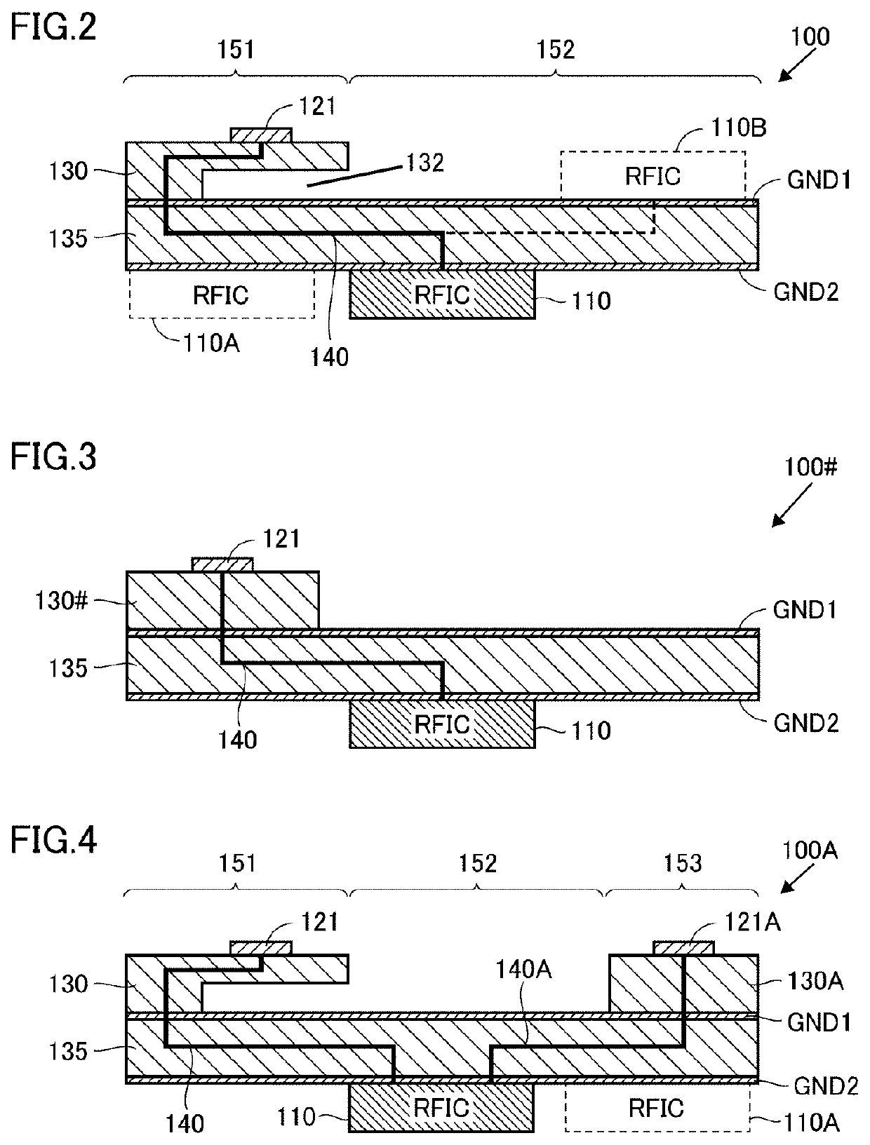
[0106]In the antenna module of the first embodiment, described is the configuration in which the dielectric layer on which the antenna element is disposed has a substantially rectangular shape when seen in a plan view, and the two antenna elements in FIG. 4, for example, are linearly arranged.

[0107]The antenna module may be used in a small and thin communication device such as a smart phone, and may be required to be disposed in a limited space in the device. In this case, depending on an attachment location of the antenna module, it may be necessary to dispose two antenna elements by offsetting the antenna elements. By doing so, in the linear antenna arrangement, there is a possibility that mechanical stress is applied to the dielectric layer and a crack or the like is generated in the dielectric layer.

[0108]Then, in the second embodiment, a configuration is described in which a dielectric layer of an antenna module is formed in a crank shape and two antenna elements are offset and...


PUM


Abstract

An antenna module (100) includes at least one antenna element (121), a ground electrode (GND1), and a dielectric layer (130), which is provided between the antenna element (121) and the ground electrode (GND1), and on which the antenna element (121) is mounted. A space (132) is formed between the dielectric layer (130) and the ground electrode (GND1) in a region where the antenna element (121) and the ground electrode (GND1) overlap each other when the dielectric layer (130) is seen in a plan view.

Description

[0001]This is a continuation of International Application No. PCT / JP2019 / 002029 filed on Jan. 23, 2019 which claims priority from Japanese Patent Application No. 2018-029845 filed on Feb. 22, 2018. The contents of these applications are incorporated herein by reference in their entireties.BACKGROUND OF THE DISCLOSUREField of the Disclosure[0002]The present disclosure relates to an antenna module and a communication device equipped with the same, and more particularly, to an antenna structure able to reduce an effective dielectric constant.Description of the Related Art[0003]WO 2016 / 067969 (Patent Document 1) discloses an antenna module in which an antenna element and a radio frequency semiconductor element are integrated to be mounted on a dielectric substrate.[0004]Patent Document 1: WO 2016 / 067969BRIEF SUMMARY OF THE DISCLOSURE[0005]In such an antenna, antenna characteristics such as a frequency band width of a transmittable radio frequency signal, a peak gain, and loss are affect...

Claims


Application Information

Patent Timeline
IPC IPC(8): H01Q1/22H01Q5/357H01Q1/38H01Q1/50
CPCH01Q1/2208H01Q1/38H01Q1/50H01Q5/357H01Q1/2283H01Q9/0407H01Q21/08H01Q21/0075
Inventor MURATA, TAKAKIONAKA, KENGOMORI, HIROTSUGU
Owner MURATA MFG CO LTD
Why Eureka
Try Eureka