
Two-stage combustor

a combustor and two-stage technology, applied in lighting and heating apparatus, combustion types, combustion using catalytic materials, etc., can solve the problems of less efficient and fragile heat transfer to a downstream application, excessive flame temperature exceeding 1,200° c, and high temperature of most metallic materials of construction, so as to reduce the amount of undesirable emissions, reduce the amount of volatilization, and reduce the effect of catalyst durability and longevity

Active Publication Date: 2022-08-16
PRECISION COMBUSTION
View PDF16 Cites 1 Cited by
  • Summary
  • Abstract
  • Description
  • Claims
  • Application Information

AI Technical Summary

Benefits of technology

This patent describes a two-stage combustor that improves the combustion of fuel in a more efficient and controlled manner. The first stage of the combustor partially oxidizes the fuel, while the second stage completes the combustion process by converting the oxidation products into carbon dioxide and water with low levels of emissions. The heat generated by the combustor is transferred efficiently to a heat acceptor, which is important for high-temperature applications such as external combustion engines. The two-stage combustor design provides several advantages, including durable and thermally efficient materials of construction, improved combustion stability, and reduced heat losses to the environment.

Problems solved by technology

Such high ratios of oxidant to fuel result in a flame temperature exceeding 1,200° C., which is too hot for most metallic materials of construction.
Under those circumstances, the combustor is required to be constructed from ceramic materials capable of withstanding the higher temperatures, but potentially more fragile and less efficient in transferring heat to a downstream application, such as the heater head of an external combustion engine (e.g., Stirling engine).
Moreover, at temperatures exceeding 1,200° C. the catalyst may be lost through volatilization.

Method used


Image

  • Two-stage combustor
  • Two-stage combustor
  • Two-stage combustor

Examples


embodiments

Example 1

[0071]An apparatus was constructed to test the efficiency of combustion and heat transfer from the deep oxidation reactor component of the instant apparatus invention to a heat acceptor simulating a heater head of a Stirling engine. With reference to the process schematic of FIG. 3, pressurized cylinders of carbon monoxide (CO) and hydrogen (H2) were connected to mass flow controllers (MFC) that metered quantities of CO and H2, respectively, into an inlet line, which fed the resulting mixture into a deep oxidation reactor (burner). The feed mixture of CO and H2 simulated a synthesis gas obtained from a POX reactor. The deep oxidation reactor / burner had disposed therein a porous foam matrix heat spreader (Metpore® brand iron-chromium alloy, SELEE Corp., density 15 percent) provided in the shape of an annulus (36 mm inner dia., 70 mm outer dia., 13 mm length). Pressurized cylinders of nitrogen (N2) and air were hooked up to mass flow controllers (MFC). A metered mixture of N2...

example 2

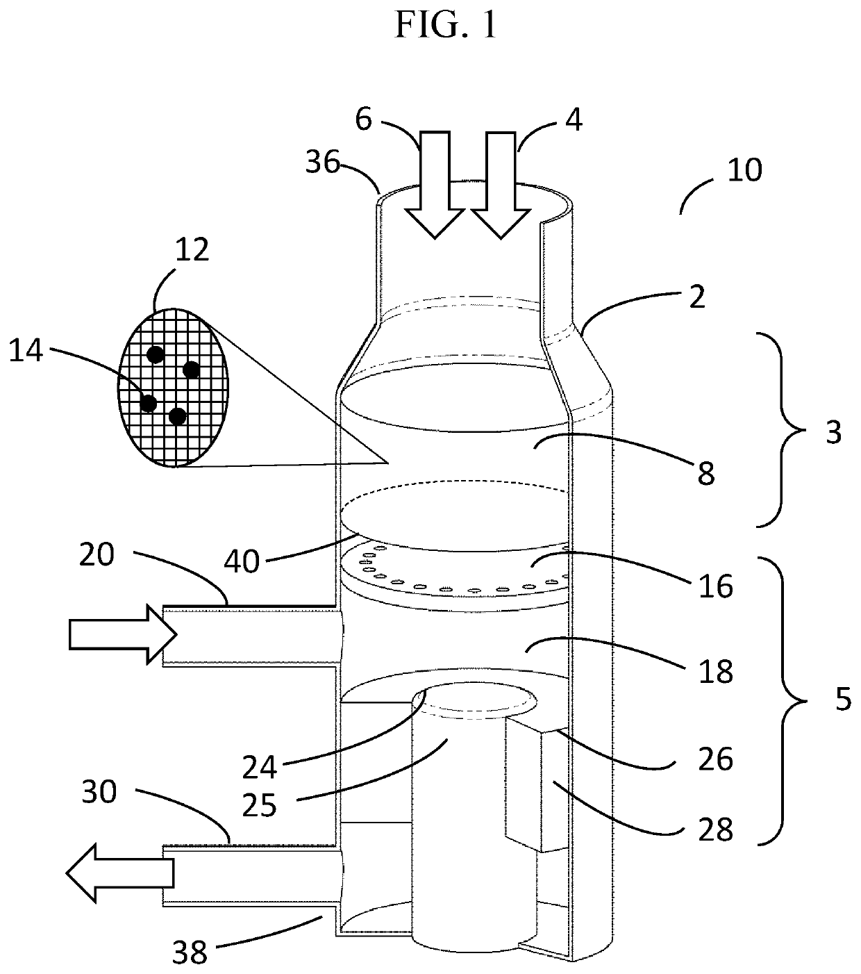
[0073]A full scale two-stage combustor was constructed and tested in accordance with this invention. The combustor featured all components of the design illustrated in FIG. 1, including the heat recuperation design shown in FIG. 2. The constructed apparatus included a housing 2 having disposed therein: a Stage 1 catalytic POX reactor 3 comprised of a fuel inlet 4 for inputting natural gas, an oxidant inlet 6 for inputting air, a partial oxidation reaction zone 8 comprising a MICROLITH brand ultra-short-channel-length metal substrate 12 having a rhodium catalyst 14 supported thereon (Precision Combustion, Inc.), and a partial oxidation reactor outlet 40; and a Stage 2 deep oxidation reactor 5 comprising a premixer plenum 18 fluidly connected to the partial oxidation reactor outlet 40, the plenum 18 having disposed therein an open-celled metal foam matrix (Metpore® brand FeCrAlY iron-chromium alloy, 100 ppi, SELEE Corp.) (not illustrated). Downstream of the premixer plenum 18 was disp...


PUM


Abstract

A two-stage combustor having as constituent parts: a partial oxidation reactor, which catalytically converts a hydrocarbon fuel and a first supply of oxidant into a gaseous partial oxidation product; and a deep oxidation reactor having a premixer plenum fluidly connected to a porous heat spreader, which converts the gaseous partial oxidation product to deep oxidation products. In one embodiment, the premixer plenum provides an empty space wherein combustion occurs in flame mode. In a second embodiment, the premixer plenum contains a high pore density foam matrix, absent catalyst, which facilitates holding a flameless combustion downstream within the porous heat spreader. In both embodiments heat produced during combustion is transmitted from the heat spreader to an associated heat acceptor, such as a heater head of a Stirling engine.

Description

CROSS-REFERENCE TO RELATED APPLICATIONS[0001]This application claims the benefit of U.S. provisional patent application No. 62 / 813,785, filed Mar. 5, 2019.GOVERNMENT RIGHTS[0002]This invention was made with support from the U.S. government under Contract No. DE-AR0000604, sponsored by the Department of Energy. The U.S. Government holds certain rights in this invention.FIELD OF THE INVENTION[0003]This invention pertains to a combustor apparatus for burning a hydrocarbon fuel with an oxidant for the purpose of producing a clean and durable combustion process while providing heat efficiently to a downstream application, for example, a heater head of an external combustion engine.BACKGROUND OF THE INVENTION[0004]Stable, non-catalytic combustion of a hydrocarbon fuel, like natural gas, at ambient pressure in a single stage combustor requires a near-stoichiometric ratio of the oxidant relative to the hydrocarbon fuel. The term “stoichiometric ratio” refers herein to an exact ratio of mole...

Claims


Application Information

Patent Timeline
Patent Type & Authority Patents(United States)
IPC IPC(8): F23D14/16F23C13/02F02G3/02F23D14/18F23C13/08F23D14/14F23C99/00
CPCF23C13/02F02G3/02F23C13/08F23C99/006F23D14/14F23D14/145F23D14/18F23D2212/10F23D2212/20F23C6/04F23C13/06
Inventor ROYCHOUDHURY, SUBIRMASTANDUNO, RICHARDCROWDER, BRUCEMACRI, FRANCESCO
Owner PRECISION COMBUSTION
Learn More