Machine component, particularly a turbomachine component, with cooling features and a method for manufacturing and of operation

a technology of turbomachine components and components, which is applied in the direction of machines/engines, lighting and heating apparatus, combustion types, etc., can solve the problems of reducing unable to withstand temperatures above 800° c, and achieve the effect of reducing the amount of air in the engine, reducing the cost of gas turbine engines, and ensuring the efficiency of gas turbine engines

Active Publication Date: 2022-06-28
SIEMENS ENERGY GLOBAL GMBH & CO KG
View PDF19 Cites 0 Cited by
  • Summary
  • Abstract
  • Description
  • Claims
  • Application Information

AI Technical Summary

Benefits of technology

[0024]Each one of a subset of the plurality of hollow struts are arranged either perpendicular to the end face or with a maximum deviation from a perpendicular direction to the end face of 45°. That means the hollow struts optionally may be angled in relation to the end face. That means if you define the orientation of the hollow strut as a Euclidian vector, you can say that the larger vector component of the vector is directed parallel to the normal of the end face whereas the smaller vector component of the vector is in direction parallel to the end face. Advantageously a hole through the end face is substantially perpendicular or angled to the end face such that a film cooling effect is avoided.
[0035]The struts provide sufficient heat conduction so that the elevated temperatures from the first section—to which all or a plurality of the struts are connected—are brought into the lattice structure via the struts. The heat internal to the struts can be conveyed by passing-by cooling fluid through the void of the lattice structure and due to the flow through the interior of the hollow struts. The void penetrated or pierced by the plurality of struts defines the flow path in form of a meander. The cooling fluid is passing by a large number of struts and thereby winds through the lattice structure and providing a good heat transfer for cooling the first section of the body of the machine component.
[0045]If the strut has only two sections, a conical section and a cylindrical section, the cone may be arranged as a truncated cone in which the truncated top may merge to the cylindrical form of the remainder of the strut without any step. In such a case, the conical part may be 5 to 50% of the overall length of the strut. The remainder of the strut may be cylindrical. This allows a good heat transfer from the first section into the lattice structure through which the cooling fluid will be guided.
[0047]Struts may intersect each other—particularly if one set of struts is angled in respect of another set of struts—or parallel struts may be connected via crossbars between the struts. This could lead to a better heat transfer and / or to a better stability of the lattice structure.
[0058]To reduce stress in the material of the body at least the solid struts could be arranged in a semi-detached way such that only one end of a respective strut is connected to the first section whereas the other end of the struts is free from further connections, particularly not connected to the third section.
[0062]In a specific embodiment a ratio between a volume of the void and a volume of solid material of the lattice structure in the second section may be reduced in direction to the end face. Therefore, a higher amount of solid material will be present closer in the direction of the first section whereas a lesser dense structure is provided in the lattice structure in the direction of the third section. This may be advantageously used to provide even a better cooling of the heated first section.

Problems solved by technology

Nevertheless, materials used typically in a gas turbine engine cannot withstand temperatures above 800° C. Therefore, these components may need to be cooled or a specific coating is required to protect the component.
The provision of cooling functionality on the other hand reduces the efficiency of the gas turbine engine.

Method used


Image

  • Machine component, particularly a turbomachine component, with cooling features and a method for manufacturing and of operation
  • Machine component, particularly a turbomachine component, with cooling features and a method for manufacturing and of operation
  • Machine component, particularly a turbomachine component, with cooling features and a method for manufacturing and of operation

Examples


Embodiment Construction

[0087]Referring now to FIG. 1, a schematic view of an exemplary gas turbine 12 is shown. The gas turbine 12 (also called gas turbine engine) comprises a compressor 13, a combustion chamber 14 and a turbine 15 as it is known per se. In this gas turbine 12 a burner 11—for example comprising a pilot burner—is arranged in front of the combustion chamber 14.

[0088]The compressor 13 compresses a fluid that is provided to the compressor 13, particularly ambient air. While compressing, the temperature of the fluid increases. Nevertheless, the compressed fluid may be used at the combustion chamber 14, at the burner 11 or in the turbine 15 for cooling purposes. In this respect this fluid may also be called cooling fluid or cooling air.

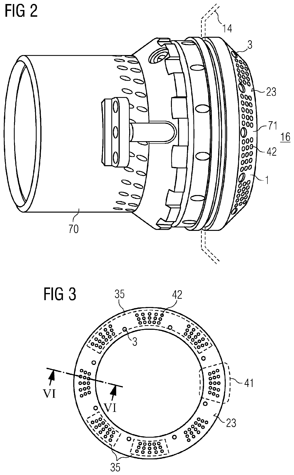
[0089]Particularly an embodiment of the invention may be applied to a burner head 70 as shown in FIG. 2, and more particularly to a pilot burner section 71, which is later on also shown in the following figures. This pilot burner section 71 is considered a cooled...


PUM

PropertyMeasurementUnit
temperaturesaaaaaaaaaa
angleaaaaaaaaaa

Abstract

A cooled machine component having a body with at least one integrated cooling channel having a lattice structure for guiding a cooling fluid through an interior, the lattice structure arranged as a void space penetrated by a plurality of hollow or solid struts. The lattice structure has an inlet for providing the cooling fluid to be guided through the void space of the lattice structure, and has an outlet for receiving the cooling fluid, the outlet being fluidically connected to a hollow interior of at least one of the plurality of hollow struts. At least a subset of the hollow struts provides a fluidic connection for cooling fluid from the outlet to a plurality of further downstream discharge ports. Walls of the body surrounding each of the plurality of further downstream discharge ports are physically connected to corresponding jackets of the at least one of the plurality of hollow struts.

Description

CROSS REFERENCE TO RELATED APPLICATIONS[0001]This application is the US National Stage of International Application No. PCT / EP2017 / 074390 filed Sep. 26, 2017, and claims the benefit thereof. The International Application claims the benefit of European Application No. EP16191801 filed Sep. 30, 2016. All of the applications are incorporated by reference herein in their entirety.FIELD OF THE INVENTION[0002]The invention relates to a machine component, particularly a gas turbine component or any turbomachine component, even more particularly a gas turbine combustor or burner component, in which a hot surface can be cooled via a specific internal hollow structure of the machine component. Furthermore the invention relates to a method for manufacturing such a component and of operation of such a component.BACKGROUND OF THE INVENTION[0003]Gas turbine engines like other rotating machines or turbomachines comprise sections in which high temperatures are experienced during operation. Also oth...

Claims


Application Information

Patent Timeline
Patent Type & Authority Patents(United States)
IPC IPC(8): F02C7/12
CPCF02C7/12F05D2220/32F23R3/002F23R3/283F23D14/78F23H3/02B23P2700/13F23D2214/00F23R2900/03043F23R2900/03045
Inventor LUNDGREN, JAN-ERIKMUNKTELL, ERIK
Owner SIEMENS ENERGY GLOBAL GMBH & CO KG
Why Eureka
Try Eureka