Passive LED matrix display driver with high dynamic range

a display driver and dynamic range technology, applied in the field of display drivers, can solve the problems of difficult or expensive design of high-resolution current digital-to-analog converters, inability to generate such a narrow pulse, and undesirable shift of emission wavelengths for displays, etc., and achieve the effect of low temperature sensitivity

Active Publication Date: 2022-06-14
DEEPSKY CORP LTD
View PDF3 Cites 0 Cited by
  • Summary
  • Abstract
  • Description
  • Claims
  • Application Information

AI Technical Summary

Benefits of technology

[0008]An aspect of the present disclosure is to provide a display driver for driving a LE matrix with a goal of delivering a high dynamic range of luminance and a high frame rate while avoiding narrow current pulses in driving the LE matrix. The LE matrix comprises plural LEs.

Problems solved by technology

The light intensity is seldom controlled by directly adjusting the current because it is more difficult or expensive to design a high-resolution current digital-to-analog converter (DAC), and that the emission wavelength of LE usually changes with the actual current going through it.
This shift of emission wavelength is undesirable for a display.
Generation of such a narrow pulse is limited by several factors, including a frequency response of the control circuit, an electrical loading of the passive-matrix display panel, and the response time of LE.
A system failing to deliver a correct ON duration leads to non-linearity in light intensity, especially at a low-light condition, resulting in an unpleasant visual effect.
However, the display driver of CN102768820 may not be able to avoid using narrow pulses if the region of image under consideration has both bright and dim details.

Method used


Image

  • Passive LED matrix display driver with high dynamic range
  • Passive LED matrix display driver with high dynamic range
  • Passive LED matrix display driver with high dynamic range

Examples


Embodiment Construction

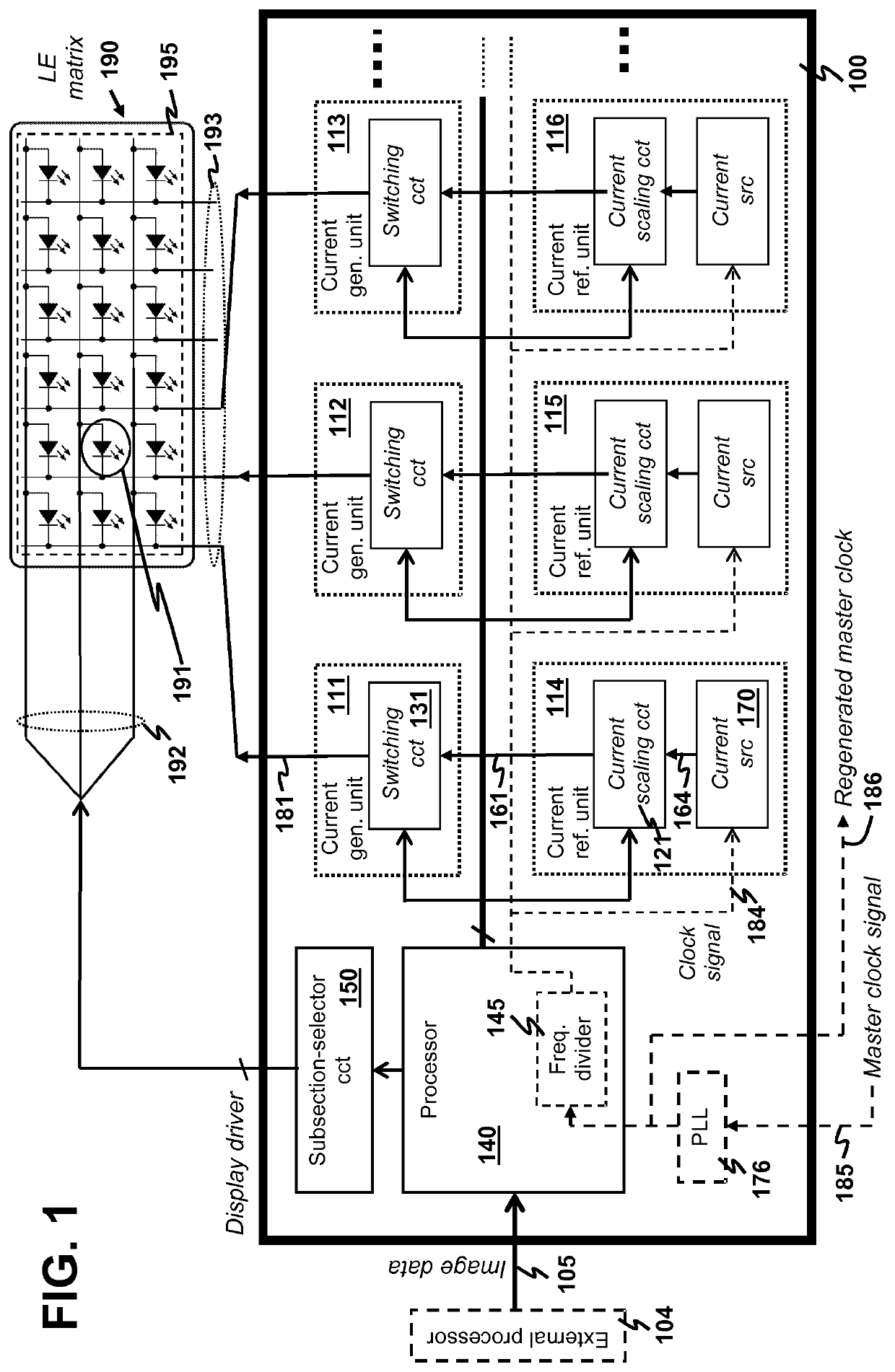
[0021]An aspect of the present disclosure is to provide a display driver for driving a passive LE matrix with a goal of delivering high dynamic range of luminance and high frame rate while avoiding using narrow pulses in driving the LE.

[0022]Exemplarily, the display driver is illustrated hereinafter with an aid of FIG. 1, which depicts an exemplary display driver 100 for driving a LE matrix 190. The LE matrix 190 as considered in illustrating the present invention comprises plural LEs 195. As one practical choice, each of the LEs includes one or more LEDs for light generation. For illustration of the display driver 100 hereinafter without loss of generality, the LE matrix 190 is divided into plural panel subsections each of which is a row such that the display driver 100 drives the rows one-by-one in a time-multiplexing manner.

[0023]In the display driver 100, a reference current is used to generate various output currents to drive the LE matrix 190.

[0024]The display driver 100 compr...


PUM


Abstract

A display driver has current reference units and current-generating units. Each current reference unit generates a reference current and scaling it to form a scaled reference current. Each current-generating unit generates an output current from one scaled reference current to drive a selected light emitter (LE) of a LE matrix over a time slice allocated for driving the selected LE. Each current-generating unit has a switching circuit modulating the scaled reference current according to a switching sequence to form output current pulses to drive a LE. The processor determines the switching sequence to avoid a shortest current pulse shorter than a minimum current pulse width via (a) calculating a duty cycle as a ratio of an average output current to the scaled reference current, (b) mapping the duty cycle to a modulation sequence, and (c) repeating stretching a time duration of the modulation sequence by double, splitting the modulation sequence into half, and allocating the split sequence into two times of original time slice, until the shortest current pulse satisfies the above-mentioned requirement.

Description

FIELD OF THE INVENTION[0001]The present disclosure relates to a display driver for driving a passive matrix of light emitters (LEs).BACKGROUND[0002]A plurality of LEs has a lot of applications, mainly but not limited to visual display. A LE can be any light emitting structure with a diode characteristic that emits light when an electrical current goes through, which can be an inorganic light emitting diode (LED), an organic LED, or a thermal emitter. LEs can be connected together as a rectangular array such that each LE is addressed by a row number and a column number, which can be referred to as a matrix. When there is any active component such as a transistor or an amplifier inside the interconnect network of the matrix, the matrix is referred to as an active matrix. In contrast, when there is no any active component inside the interconnect network of the matrix, the matrix is referred to as a passive matrix. A passive matrix can be divided into a plurality of panel subsections ea...

Claims


Application Information

Patent Timeline
Patent Type & Authority Patents(United States)
IPC IPC(8): G09G3/32
CPCG09G3/32G09G2300/06G09G3/2025G09G3/2081G09G3/3216G09G3/3283G09G2310/0272
Inventor COLLOT, LAURENTCHENG, WAI KIN
Owner DEEPSKY CORP LTD
Why Eureka
Try Eureka