Image display method, device and projection device

An image display device and image display technology, applied in the field of projection, can solve the problems of poor expression of details in the dark field of projected images, etc., and achieve the effects of improving the brightness range, saving energy reasonably, and satisfying the display brightness

Active Publication Date: 2022-04-22
APPOTRONICS CORP LTD
View PDF0 Cites 0 Cited by
  • Summary
  • Abstract
  • Description
  • Claims
  • Application Information

AI Technical Summary

Problems solved by technology

[0003] In order to solve the technical problem of poor expression of dark field details of projected images when existing projection equipment realizes high dynamic range display effects, the present invention provides an image display method, device and projection equipment

Method used


Image

  • Image display method, device and projection device
  • Image display method, device and projection device
  • Image display method, device and projection device

Examples


Embodiment Construction

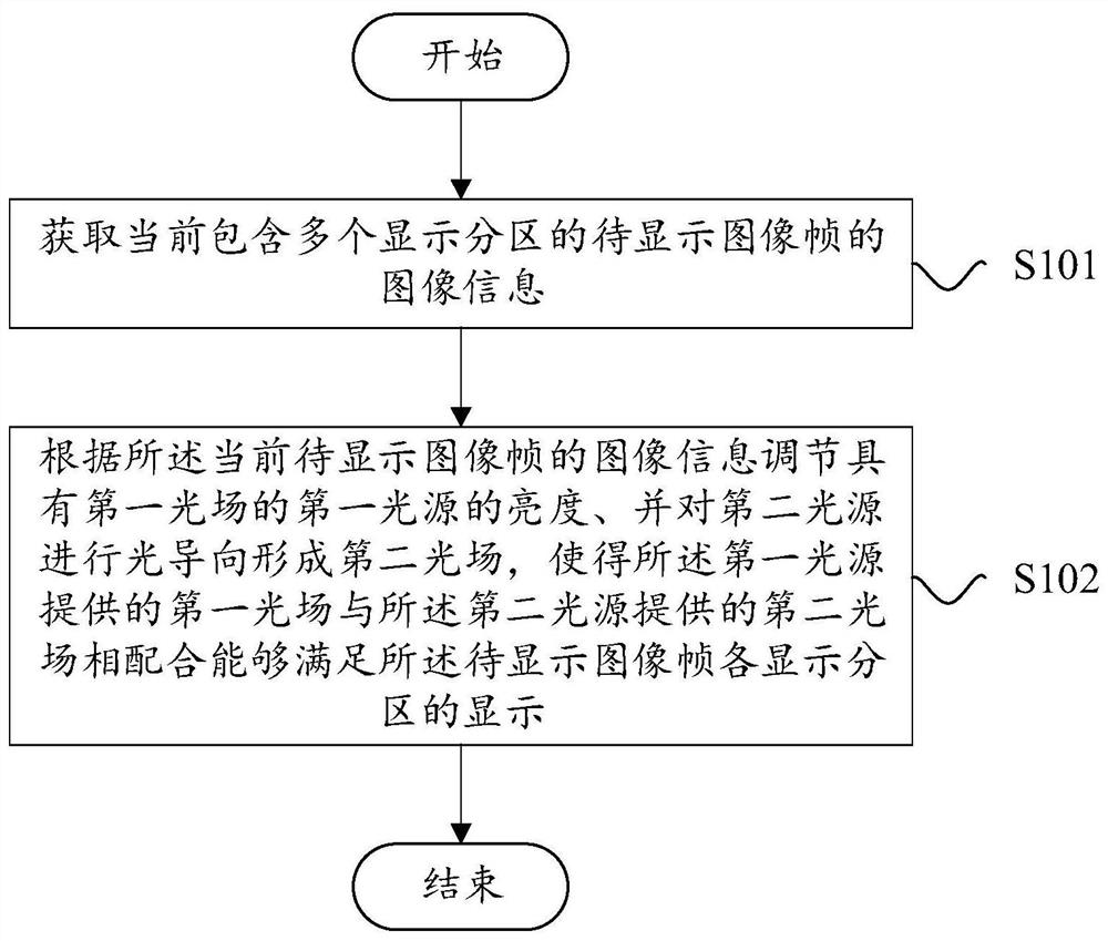
[0046] see figure 1 , figure 1 It is a flow chart of the image display method provided by the present invention in the first embodiment. The image display method can be applied to image display devices and projection equipment including the image display device, such as cinema machines, laser TVs, engineering machines, business education machines, video walls, and micro-projection equipment.

[0047] The image display method of this embodiment is applicable, and the image display device may include a first light source and a second light source, so as to provide specific brightness through the cooperation of the first light source and the second light source. Such as figure 1 As shown, the image display method in this embodiment may include the following steps:

[0048] S101: Acquire image information of an image frame to be displayed that currently includes multiple display partitions.

[0049] In this embodiment, the display partition is a partition obtained by dividing ...


PUM


Abstract

The present invention relates to an image display method, device, and projection equipment. The image display method includes: acquiring image information of an image frame to be displayed currently including a plurality of display partitions; the brightness of the first light source in the first light field, and guide the second light source to form a second light field, so that the first light field provided by the first light source is equal to the second light field provided by the second light source The coordination can satisfy the display of each display partition of the image frame to be displayed. The present invention can be beneficial to realize the high dynamic range display of the image, and is also beneficial to improve the dark field detail expression of the image to be displayed.

Description

technical field [0001] The present invention relates to the field of projection technology, in particular to an image display method, device and projection equipment. Background technique [0002] In the application technology of projection equipment to realize high dynamic range display, if there is a technical solution: use part of the light for light-guided high dynamic range display projection equipment, 70% of the light from the light source is directly provided to the digital micromirror spatial light modulator , and 30% of the light is provided to the silicon-based liquid crystal chip for light guidance and then illuminates the digital micromirror spatial light modulator, thereby increasing the local brightness of the projected image. This technology can improve the peak brightness of the projected image and increase the color gradation and brightness of the bright field part. However, the dark field of the projected image is still bright, and the details of the dark ...

Claims


Application Information

Patent Timeline
Patent Type & Authority Patents(China)
IPC IPC(8): G03B21/20
CPCG03B21/2013G03B21/2053G09G3/002G09G3/3406G09G2320/0238H04N9/3155H04N9/3164H04N9/3126H04N9/3182H04N9/3105H04N9/3152H04N9/3158H04N9/3161
Inventor 余新吴超胡飞李屹
Owner APPOTRONICS CORP LTD
Why Eureka
Try Eureka