Low drag, variable-depth acoustic liner

a acoustic liner and low drag technology, applied in the field of low drag and variable depth acoustic liner, can solve the problems of limiting operations, affecting the expansion of the aviation sector, and affecting the health of the public in the vicinity of airports, so as to reduce or attenuate acoustic radiation, improve broadband acoustic performance, and reduce noise

Active Publication Date: 2022-06-07
NASA
View PDF40 Cites 1 Cited by
  • Summary
  • Abstract
  • Description
  • Claims
  • Application Information

AI Technical Summary

Benefits of technology

[0007]Systems and devices of the various embodiments may provide a low-drag, variable-depth acoustic liner having shared inlet volumes. Various embodiments may include a low-drag, variable-depth acoustic liner providing source (e.g., an aircraft, a car, etc.) noise reduction. Acoustic liners according to the various embodiments may be used in engine nacelles and / or on external surfaces of an aircraft or on surfaces of other noisy systems to reduce or attenuate acoustic radiation. Acoustic liners according to various embodiments may provide increased broadband acoustic performance with less drag than conventional liners. Various embodiments may provide an acoustic liner with reduced facesheet open area, and therefore reduced liner drag, when compared with conventional acoustic liners.

Problems solved by technology

Aircraft noise can have a detrimental impact on public health in communities near airports.
As a result, many airports limit operations (i.e., takeoffs and landings) to reduce community noise exposure.
These restrictions inhibit the expansion of the aviation sector, which is an important driver of the U.S. economy.
A perforated facesheet, however, has a higher drag than a smooth surface.
The perforated facesheet can also be costly to manufacture.
The perforated facesheet on a large nacelle liner can contain several hundred thousand holes (or slots), which are time consuming and costly to machine.

Method used


Image

  • Low drag, variable-depth acoustic liner
  • Low drag, variable-depth acoustic liner
  • Low drag, variable-depth acoustic liner

Examples


Embodiment Construction

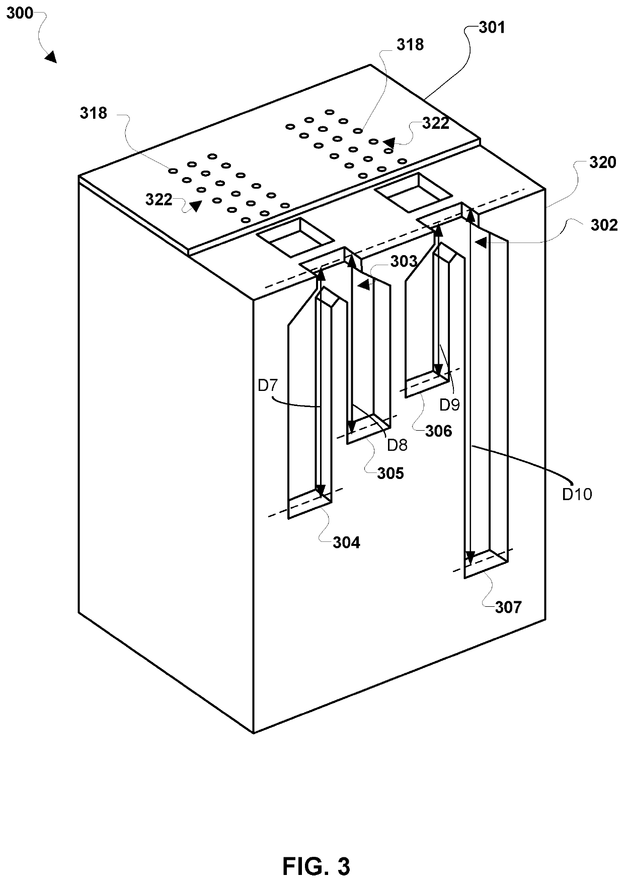
[0025]For purposes of description herein, the terms “upper,”“lower,”“right,”“left,”“rear,”“front,”“vertical,”“horizontal,” and derivatives thereof shall relate to the invention as oriented in FIG. 3. However, it is to be understood that the invention may assume various alternative orientations and step sequences, except where expressly specified to the contrary. It is also to be understood that the specific devices and processes illustrated in the attached drawings, and described in the following specification, are simply exemplary embodiments of the inventive concepts defined in the appended claims. Hence, specific dimensions and other physical characteristics relating to the embodiments disclosed herein are not to be considered as limiting, unless the claims expressly state otherwise.

[0026]The word “exemplary” is used herein to mean “serving as an example, instance, or illustration.” Any implementation described herein as “exemplary” or as an “embodiment” is not necessarily to be ...


PUM


Abstract

Systems and devices of the various embodiments may provide a low-drag, variable-depth acoustic liner having shared inlet volumes. Various embodiments may include a low-drag, variable-depth acoustic liner providing aircraft noise reduction. Acoustic liners according to the various embodiments may be used in engine nacelles and / or on external surfaces of an aircraft to reduce acoustic radiation. Acoustic liners according to various embodiments may provide increased broadband acoustic performance with less drag than conventional liners. Various embodiments may provide an acoustic liner with a reduced open area of the facesheet, and therefore reduced drag of the liner, when compared with conventional acoustic liners.

Description

CROSS-REFERENCE TO RELATED PATENT APPLICATION[0001]This patent application claims the benefit of and priority to U.S. Provisional Application No. 62 / 740,001, filed on Oct. 2, 2018, the contents of which are hereby incorporated by reference in their entirety.STATEMENT REGARDING FEDERALLY SPONSORED RESEARCH OR DEVELOPMENT[0002]The invention described herein was made by employees of the United States Government and may be manufactured and used by or for the Government of the United States of America for governmental purposes without the payment of any royalties thereon or therefore.BACKGROUND OF THE INVENTION[0003]Aircraft noise can have a detrimental impact on public health in communities near airports. As a result, many airports limit operations (i.e., takeoffs and landings) to reduce community noise exposure. These restrictions inhibit the expansion of the aviation sector, which is an important driver of the U.S. economy. The development of new technologies capable of reducing aircr...

Claims


Application Information

Patent Timeline
Patent Type & Authority Patents(United States)
IPC IPC(8): F24F13/24G10K11/162B64D33/02B60R13/08
CPCF24F13/24B60R13/08B64D33/02G10K11/162B64D2033/0206B64D2033/0286F24F2013/242F24F2013/245G10K11/172
Inventor SCHILLER, NOAH H.JONES, MICHAEL GHOWERTON, BRIAN M.NARK, DOUGLAS M.
Owner NASA
Why Eureka
Try Eureka